45
If the stem to guide clearance exceeds the service limit:
Determine if the new guide with standard dimensions would bring the clearance within tol-
erance, if so replace any guide as necessary and ream to fit. If the stem to guide clearance
exceeds the service limit with new guides, replace the valves also.
NOTE: Recondition the valve seats when valve guides are replaced.
VALVE GUIDE REPLACEMENT
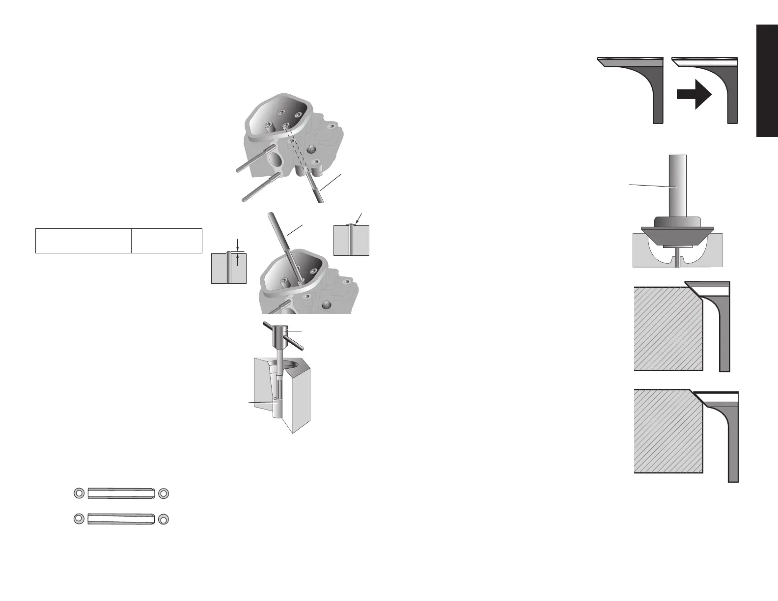
1. Drive the valve guides out of the head from
the combustion chamber side using a
valve guide driver.
2. Install the new valve guides from the
valve spring side of the cylinder head.
Exhaust side: Drive the exhaust valve
guide until the clip is fully seated as
shown.
Intake side: Drive the intake valve
guide to the specified height (measure
from the top of the valve guide to the
cylindercastingasshown)
IN valve guide
installation height
3.0mm(0.12")
3. After installation, inspect the valve guide
IN: 3.0 mm
.012 in
EX: CLIP
for damage, replace if necessary.
VALVE GUIDE REAMING
1. Coat the reamer and valve guide with
cutting oil.
2.Rotate the reamer clockwise through
the valve guide the full length of the
reamer.
3.Continuetorotatethereamerclockwise
while removing it from the valve guide.
4. Thoroughly clean the cylinder head
to remove any cutting oil residue and
chips.
5.Check thevalveguide bore: it should
be straight, round and centered in
the valve guide. Insert the valve and check operation. If the valvedoes not operate
smoothly, the guide may have been bent during installation. Replace the valve guide if
it is bent or damaged.
6.ChecktheValveGuidetoStemClearance.
VALVE SEAT RECONDITIONING
1. Clean the combustion chamber and valve
seats(V8)toremovecarbondeposits.
2. Apply a light coat of Prussian Blue or eras-
ablefelt-tippedmarkeronvalveface.
3. Insert the valve and snap it closed against
the seat several times. Ensure the valve does
notrotateontheseat.Thetransferredmark-
ing compound will show any area of the seat
this is not concentric.
NOTE: Follow the valve seat cutter manufacture
instructions.
4. Use a 45° cutter to remove enough material
to produce a smooth and concentric seat.
Turn the cutter clockwise, never counterclockwise.
Continue to turn the cutter while lifting it from the valve
seat.
5. Use a 30° – 32° and 60° cutter to narrow and adjust the
valve seat so it contacts the middle of the valve face.
Use a 30° – 32° cutter to remove material from the
bottomedge(contacttoolow).
Use a 60° cutter to remove material from the top edge
(contact too high). Ensure the width of the finished
valve seat is within specifications.
V8
VALVE
SEAT
CUTTER
VALVE
GUIDE
DRIVER
REAMING TOOL
VALVE
GUIDE
CORRECT
INCORRECT