51
PISTON PIN TO PISTON PIN BORE CLEARANCE
STANDARD (MM) SERVICE LIMIT (MM)
0.004~0.016 0.08
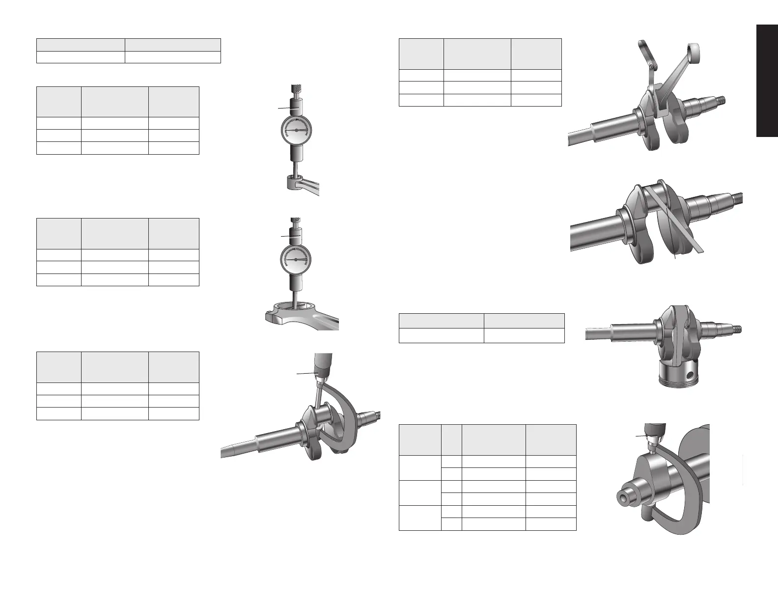
CONNECTING ROD SMALL END I. D.
MODEL
STANDARD
(MM)
SERVICE
LIMIT
(MM)
dW168
18.011~18.022 18.06
dW177
18.011~18.022 18.06
dW188
20.011~20.022 20.06
CONNECTING ROD BIG END I. D.
MODEL
STANDARD
(MM)
SERVICE
LIMIT
(MM)
dW168
30.02~30.03 30.06
dW177
33.02~33.03 33.06
dW188
36.02~36.03 36.06
CRANKPIN O. D.
MODEL
STANDARD
(MM)
SERVICE
LIMIT
(MM)
dW168
30.00 29.94
dW177
33.00 32.94
dW188
36.00 35.94
CONNECTING ROD BIG END SIDE CLEARANCE
MODEL
STANDARD
(MM)
SERVICE
LIMIT
(MM)
dW168
0.95~1.45 1.85
dW177
0.55~1.25 1.65
dW188
0.55~1.25 1.65
CONNECTING ROD BIG END OIL CLEARANCE
1.Clean all oil from the crank pin and
PLASTIGAUGE
connecting rod big end surfaces.
2. Place a piece of plastigauge on the
crankpin.
3. Install the connecting rod and cap.
4.Tightentheboltsandtorqueto12N•m
|(1.2Kg-m,9ft.-lbs.).
NOTE:Donotrotatethecrankshaftwiththe
plastigauge in place.
5. Remove the connecting rod and measure
the plastigauge.
STANDARD SERVICE LIMIT
0.04
~
.066 0.12
6. If the clearance exceeds the service limit,
replacetheconnectingrodandrecheckthe
clearance.
CAMSHAFT CAM HEIGHT
MODEL
STANDARD
(MM)
SERVICE
LIMIT
(MM)
dW168
IN
27.700 27.45
EX
27.747 27.50
dW177
IN
31.716 31.35
EX
31.754 31.35
dW188
IN
32.585 32.25
EX
32.068 31.80
MICROMETER
MICROMETER
DIAL INDICATOR
BORE GAUGE
DIAL INDICATOR
BORE GAUGE