ConnectCore for i.MX51
©2011DigiInternational,Inc. 72
Two 2 x 10 pin headers, X15 and X17, are provided on the development board for connecting
two Digi camera application kits (optional) or customer specific hardware.
X15 connector for camera 1
X17 connector for camera 2
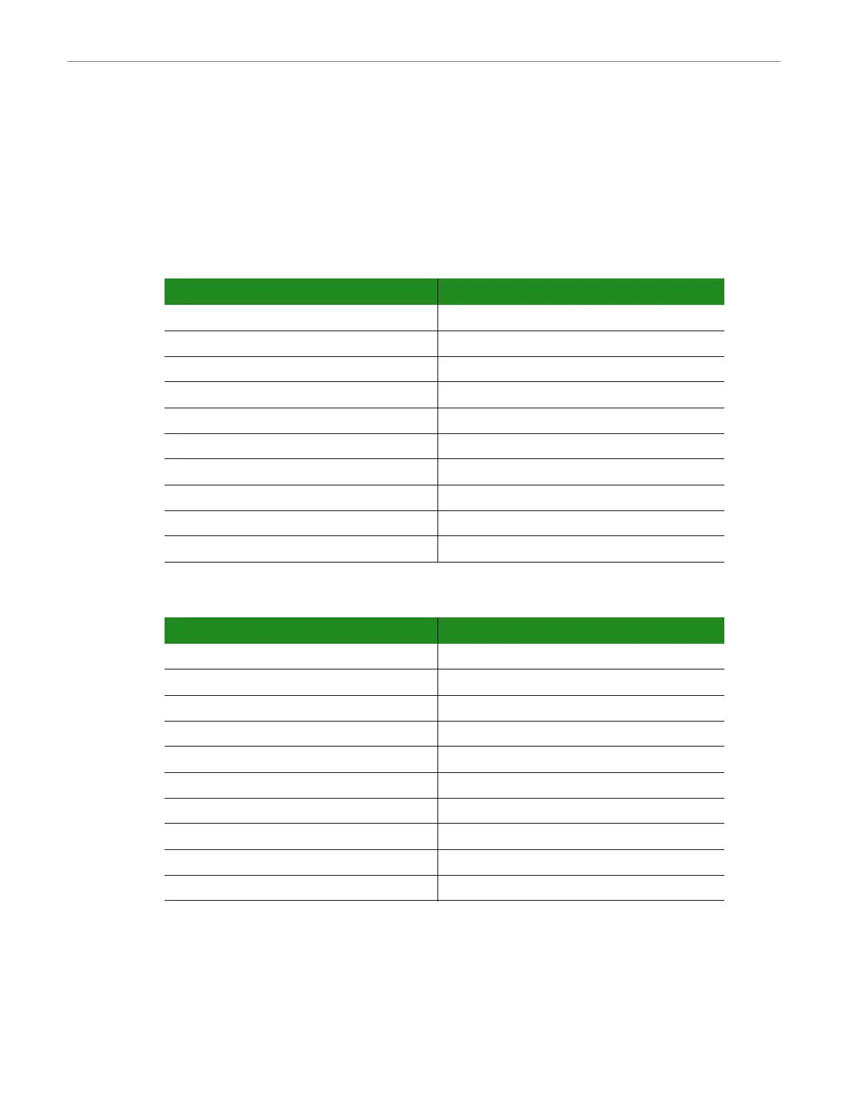
X15 Pinout
X17 Pinout
Pin Signal Pin Signal
1 +2.775V 2 GND
3 CSI1_D12 4 CSI1_D13
5 CSI1_D14 6 CSI1_D15
7 CSI1_D16 8 CSI1_D17
9 CSI1_D18 10 CSI1_D19
11 CSI1_MCLK 12 CSI1_PIXCLK
13 CSI1_HSYNC/GPIO3_15 14 CSI1_VSYNC/GPIO3_14
15 GPIO1_2/I2C2_SCL 16 GPIO1_3/I2C2_SDA
17 CSI1_D10 18 CAMRESET1#/GPIO3_13/CSI1_D19
19 GND 20 CSI1_D11
Pin Signal Pin Signal
1 +2.775V 2 GND
3 CSI2_D12/GPIO4_9 4 CSI2_D13/GPIO4_10
5 CSI2_D14 6 CSI2_D15
7 CSI2_D16 8 CSI2_D17
9 CSI2_D18/GPIO4_11 10 CSI2_D19/GPIO4_12
11 CSI1_MCLK 12 CSI2_PIXCLK/GPIO4_15
13 CSI2_HSYNC/GPIO4_14 14 CSI2_VSYNC/GPIO4_13
15 GPIO1_2/I2SC2_SCL 16 GPIO1_3/I2C2_SDA
17 - 18 CAMRESET2#/APIO3_7
19 GND 20 -