ConnectCore for i.MX51
©2011DigiInternational,Inc. 86
LCD 1 Connector, P1
This connector provides access to the following capabilities:
18-bit (RGB x 8bit) LCD
SPI bus for a touch screen controller
Touch screen (on-module, shared with LCD2)
Interrupt input for touch screen
I
2
C bus
2 x GPIO
+3.3VDC supply and a 9-30VDC supply
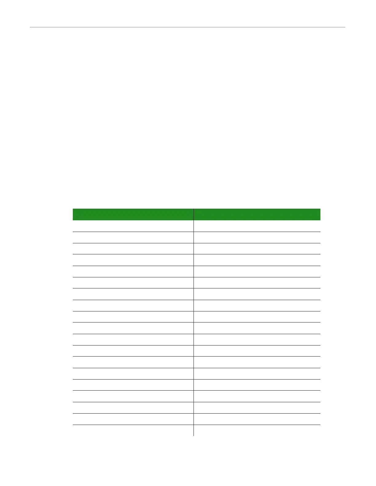
P1 Pinout
The table below shows the pinout of the LCD1 connector, P1:
Pin Function Pin Function
1 LCD1_DATA16 (R0) 2 LCD1_DATA17 (R1)
3 LCD1_DATA12 (R2) 4 LCD1_DATA13 (R3)
5 LCD1_DATA14 (R4) 6 LCD1_DATA215(R5)
7 LCD1_DATA16 (R6) 8 LCD1_DATA17 (R7)
9- 10-
11 - 12 -
13 GND 14 GND
15 LCD1_DATA10 (G0) 16 LCD1_DATA11 (G1)
17 LCD1_DATA6 (G2) 18 LCD1_DATA7 (G3)
19 LCD1_DATA8 (G4) 20 LCD1_DATA9 (G5)
21 LCD1_DATA10 (G6) 22 LCD1_DATA11 (G7)
23 - 24 -
25 - 26 -
27 GND 28 GND
29 LCD1_DATA4 (B0) 30 LCD1_DATA5 (B1)
31 LCD1_DATA0 (B2) 32 LCD1_DATA1 (B3)
33 LCD1_DATA2 (B4) 34 LCD1_DATA3 (B5)
35 LCD1_DATA4 (B6) 36 LCD1_DATA75 (B7)
37 - 38 -