DG-BG1000 User Manual
10
Step 3 Plug one end of the power adapter to the wall outlet and connect the
other end to the Power interface of the device.
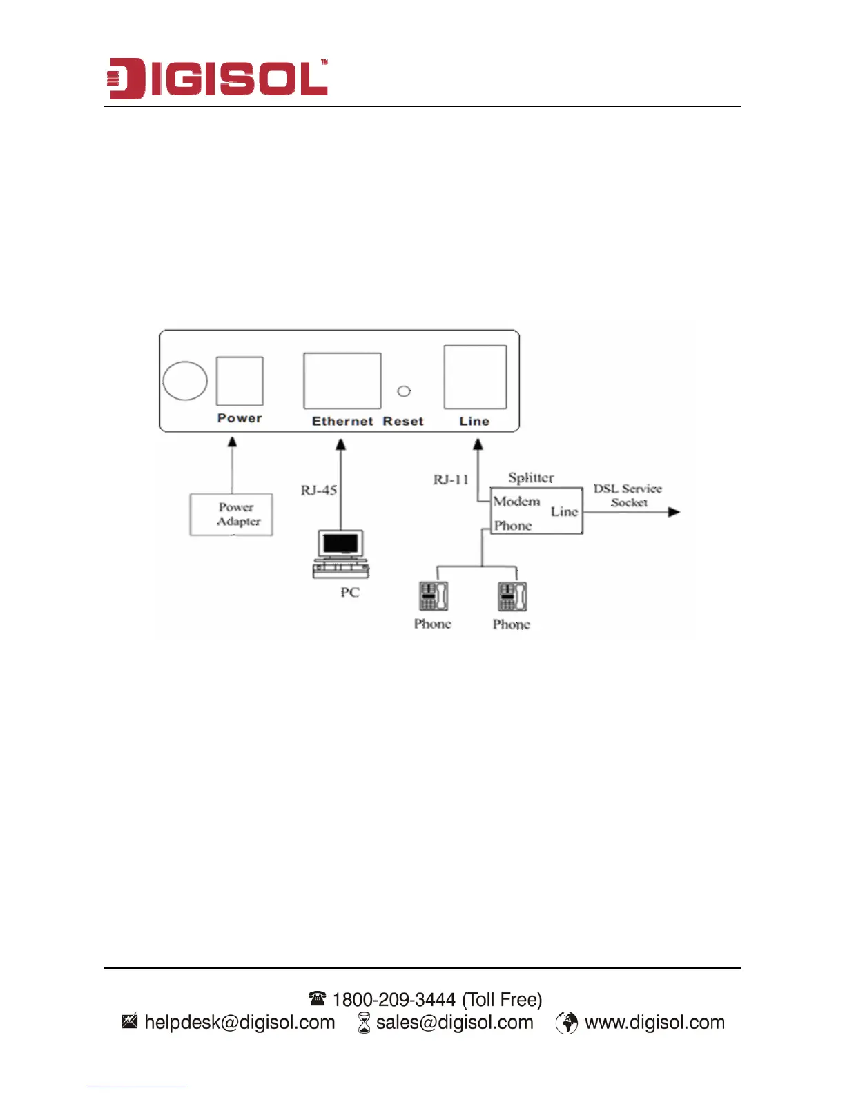
Connection 1
Figure 1 shows the application diagram for the connection of the router, PC, splitter
and the telephone sets, when no telephone set is placed before the splitter.
Figure 1 Connection diagram (Without connecting telephone sets before the splitter)