Cords colors in a scheme:
Y – yellow;
R – red;
G – green;
B – black;
Bl – blue;
W – white;
Gr– grey.
1) Electric starter button; 2) Starter; 3) Start relay; 4) Accumulator battery 12V9Ah; 5) Ignition lock;
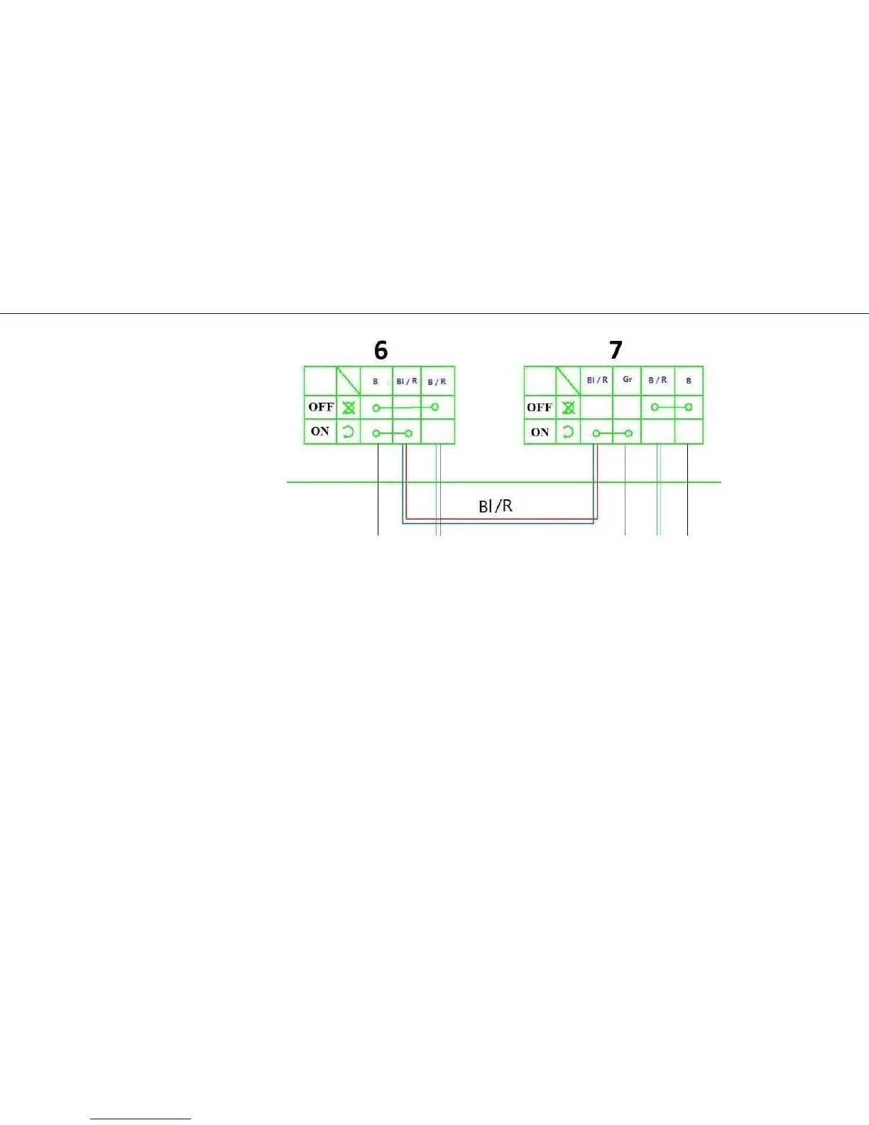
6) Ignition emergency stop switch (pin, right block of wheel switches); 7) Key off
(left block of wheel switches); 8) Regulator-voltage rectifier; 9) Electronic ignition unit;
10) Engaged gear detector; 11) Cutout; 12) Buzz ; 13) Engine coil ; 14) Battery discharge indicator light; 15) A switched on neutral
indicator light; 16) Back run switching on indicator light; 17) Environmental temperature indicator; 18) Speedometer / Tachometer;
19) Position lights indicator; 20) Low-high beam lamp, H4 12V 35W (head lighting); 21) Position lights lamp, 12V3W; 22)
Environmental temperature detector; 23) Brake lever detector; 24) Position lights switching on detector; 25) Left block of wheel
switches. Low-high beam switch; 26) Carburetor inlet barrel heating; 27) Carburetor fortifier; 28) Speed sensor; 29)Socket for
outer equipment connection, 12V; 30) stop lamp / tail lamp; 31) Wheel grips of a wheel and a gas cock heating switch; 32) Wheel
grips of a wheel and a gas cock heating indicator light; 33) Gas cock heating component; 34) Left and right wheel grips heating
component; 35) Generator; 36) Spark plug.
42