OPERATION
71
METAL DETECTION PROCEDURE
When a ferrous material is detected, the alarm is activated and the feed rolls and header are stopped within milliseconds.
The transmission will also shift to NEUTRAL automatically. The transmission overload clutch will momentarily emit a loud
clacking while the transmission shifts to Neutral. In this case:
1. An intermittent alarm resounds (refer to the legend on the side of the control box). Stop the tractor and reduce
the engine speed.
2. Make sure the transmission is in NEUTRAL.
3. Stop the PTO and the tractor.
4. Put on the park brakes and block the harvester wheels.
5. Remove the key from the tractor and carry them with you.
6. Wait until the rotating components have completely stopped.
7. Manually remove the plants from the header (the metal that caused the alarm is not in this section of the
machine).
8. Manually rotate the feed rolls to expel the crop caught between them. The metal part will be found in this section.
It may be difficult to locate the smaller metal part in the crop, or the part may have fallen to the ground or
between the bottom feed rolls.
9. INITIALIZING THE METAL DETECTOR (see section INITIALIZING THE METAL DETECTOR, page 70 and resume
harvesting.
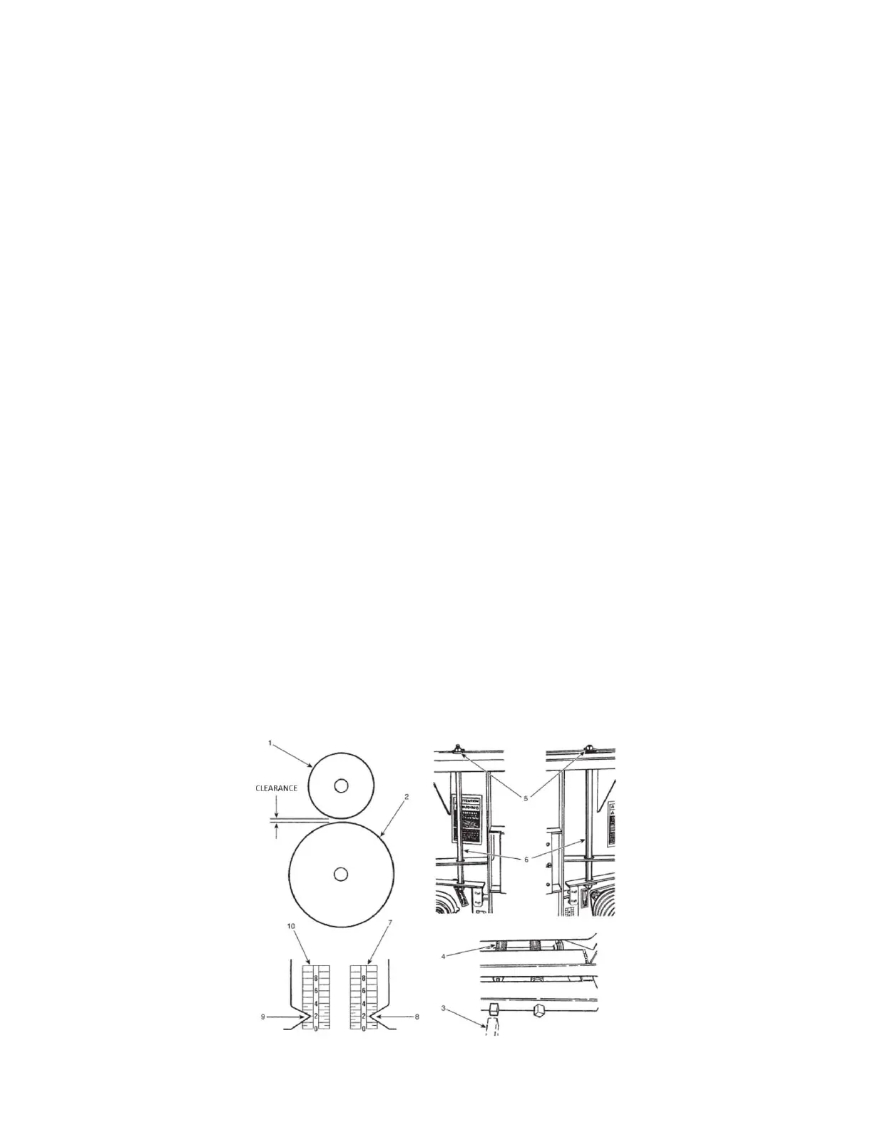
PROCESSOR ROLL PRESSURE AND SPACING
The operator can select the silage condition by varying the pressure and clearance of the upper processor roll (item 1).
Refer to FIGURE 84.
1. Adjust the pressure using the square headed handle (item 3).
2. Turn the left-hand spring threaded rod (item 4) until a 1.5 mm (1/16”) space is obtained between the spring coils.
3. Adjust the upper roll gap by the elastic stop nuts (item 5, on both sides) on both of the vertical adjusting rods
(item 6). Ensure the tension applied to the rods is equal on both sides.
4. Adjust the nuts equally to achieve the same indicator limit (Items 7 & 10).
NOTE: The adjustment is done mainly by varying the processor roll clearance.
NOTE: A linkage system maintains the rolls parallel and a uniform clearance over the width of the rollers.
Figure 84 Processor roll clearance and pressure
 Loading...