10
© 2009 Directed Electronics. All rights reserved.
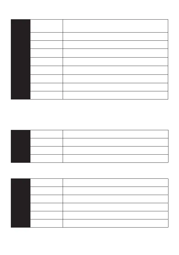
➢ Primary harness (H1) wiring diagram
H1/1
LIGHT GREEN/
BLACK
(-) FACTORY ALARM DISARM
H1/2
GREEN/WHITE (-) FACTORY REARM
H1/3
YELLOW (+) IGNITION OUT (TO ALARM)
H1/4
WHITE/BLUE
(-) ACTIVATION INPUT
*
H1/5
ORANGE
(-) GROUND WHEN LOCKED
*
H1/6
BROWN
(-) HORN OUTPUT
*
H1/7
RED/WHITE
(-) TRUNK RELEASE OUTPUT
*
H1/8
BLACK GROUND
H1/9
WHITE (+/-) LIGHT FLASH
*Not available with 1- button remote
➢ 4-pin satellite harness diagram
1
BLUE (-) STATUS OUTPUT
2
ORANGE (-) ACCESSORY OUTPUT
3
PURPLE (-) STARTER OUTPUT
4
PINK (-) IGNITION OUTPUT
➢ Heavy gauge relay wiring diagram
1
PINK (+) OUTPUT TO IGNITION CIRCUIT
2
PURPLE (+) OUTPUT TO STARTER CIRCUIT
3
ORANGE (+) OUTPUT TO ACCESSORY CIRCUIT
4
RED (+) (30A)) HIGH CURRENT 12 INPUT
5
PINK/WHITE (+) PROGRAMMABLE OUTPUT FOR ACCESSORY OR IGNITION
6
RED (+) (30A) HIGH CURRENT 12V INPUT