A-7
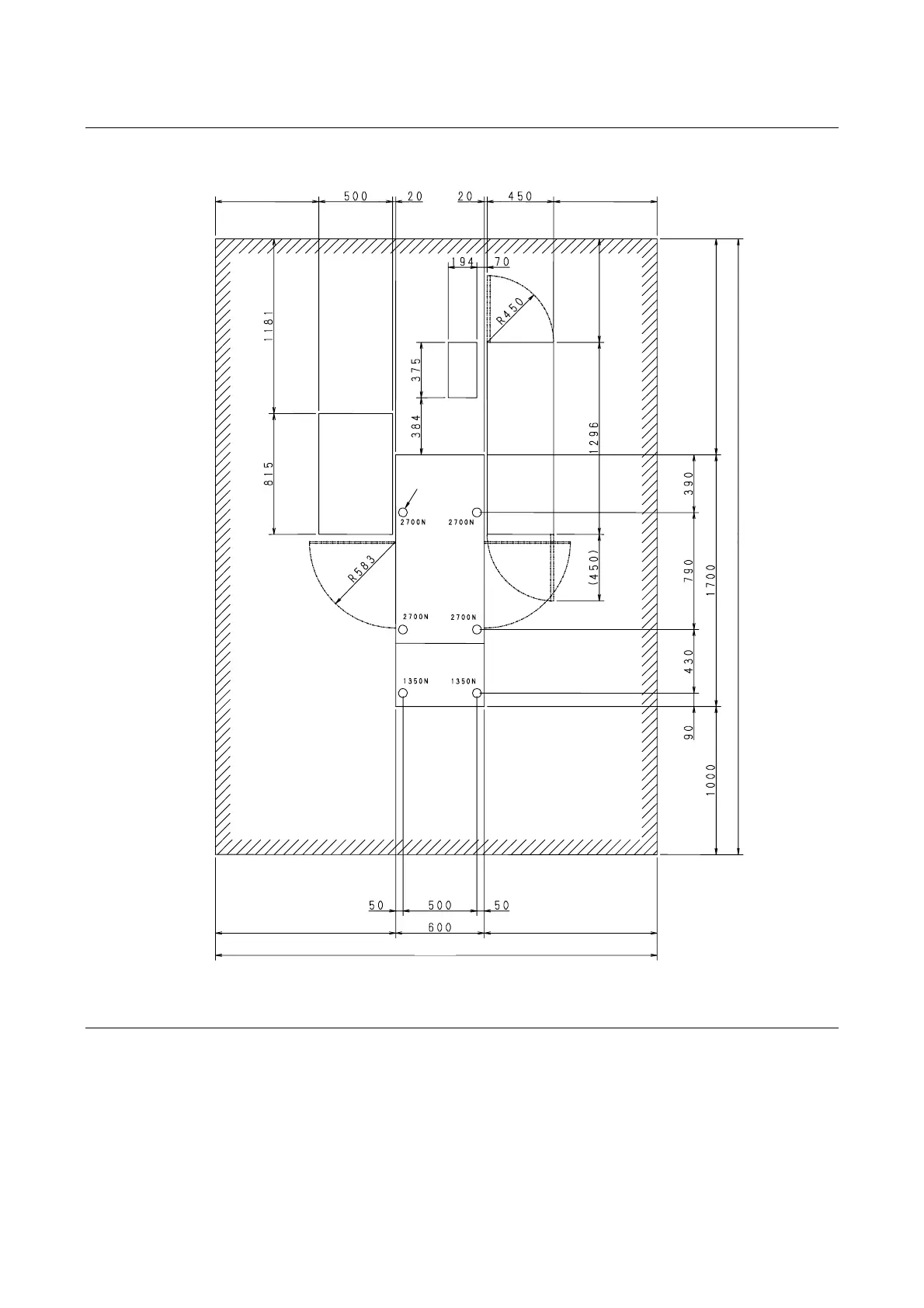
Installation diagram when the optional accessory are used
The installation diagram of DAG810 when the vacuum unit, water temperature control unit and UPS
(optional accessories) are used is shown.
UPS
water
temperature
control unit
vacuum
unit
Unit:mm
(*1): The booster pump [optional accessory] is incorporated into the vacuum unit.
(*2): The duct unit [optional accessory] is installed on the vacuum unit.
Operation
Maintenance
area
Adjuster feet (6)
690690
690
1449
4149
11601210
2970