B-18
Equipment you must have ready
The following tools as well as the joints should be readied to make piping connection to the machine.
Joints for making connection at the plant facility side are also required separately.
Adjustable wrench
Wrench
Silicone sealant
Joint
for 19 × 26 braided hose: Rc3/4 (1 pc.)
for 15 × 22 braided hose: Rc3/8 (1 pc.)
for 12 × 18 braided hose: Rc1/4 (1 pc.)
for 9 × 15 braided hose: Rc1/4 (1 pc.)
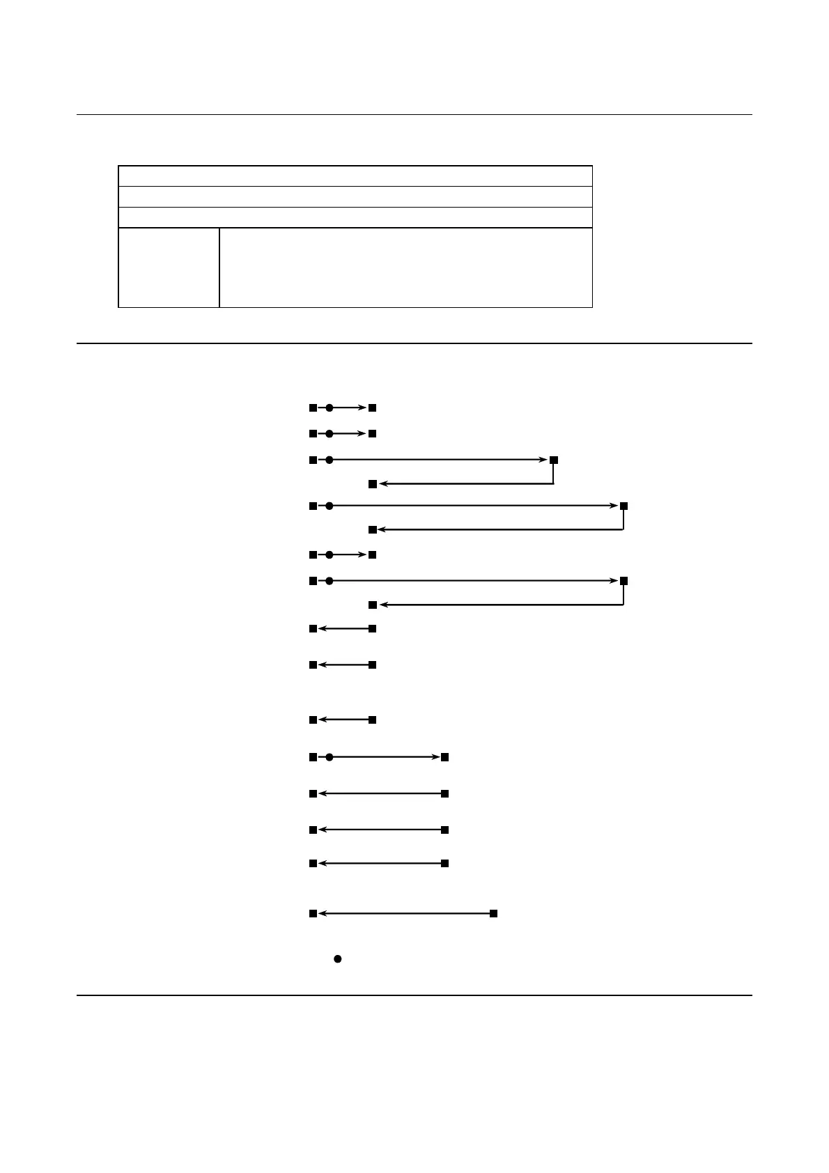
Piping system diagram
Main air supply
Facility Machine
main body
Vacuum *
unit
Duct *
unit
Booster *
pump
DTU152 *
(*) Optional accessory
Lockout must be made at the plant facility side.
Wheel coolant
water supply
(When the booster pump and DTU152 are not used.)
(When the booster pump is used.)
(When DTU152 is used.)
Spindle coolant
water supply
(When DTU152 is not used.)
(When DTU152 is used.)
Spindle coolant
water drainage
Wheel coolant
and cleaning
water drainage
Machine main
body air exhaust
Vacuum unit
water supply
Vacuum unit
water drainage
Vacuum unit air
exhaust
Vacuum unit
drain pan
drainage
(Drain pan)
Duct unit air
exhaust