Output Value Description
0 -
1 +
24 V= / 0,5 A (max)
Accessories power supply. External accessories power supply output.
Note: the maximum absorption of 0.5 A corresponds to the sum of all terminals 1.
COM Allows the connection of possible commands for distances under 4,5 m.
0 -
1 +
21
22
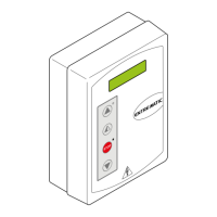
Allows the connection of 1 or 2 COME selector switches or the display
or the connection of the DMCS software,
or the network connection of a maximum of 4 automations.
Note: use a data transmission type screened cable.
FUTURE USE
OPEN OPENING The opening operation is activated with a brief press.
SETTINGS RESET Keep the OPEN button pressed (for 4 s), until the IN LED starts to ash. To
conrm the operation, press the OPEN button again for 2 seconds within 4
seconds.
The SETTINGS RESET annuls all the remote software settings made via
DMCS, MD1, TEL2, COME. After SETTINGS RESET it is possible to adjust
the control panel directly.
- MOT +
ENCODER
Motor-encoder connection. Connect the motor and encoder to the control
panel by means of the supplied cables.
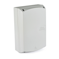
POWER AL2 power supply unit connection.
VALABE 2 x 12 V / 1,2 Ah Anti-panic battery kit (VALABE). With DIP3=OFF with the mains power sup-
ply off, the automation will carry out an opening operation at low speed. When
the door is open the power supply is disconnected from the control panel.
To charge the batteries, connect the mains power and the battery kit at least 30
minutes before starting the system.
Warning: to allow charging, the battery kit must be connected to the control
panel at all times. Periodically check the efciency of the battery kit.
VALABC 2 x 12 V / 7 Ah Continuous mode battery kit (VALABC). Con DIP3=ON with the mains po-
wer supply off, the battery kit will guarantee continuous operation.
With DIP4 select the last operation with the batteries at.
To charge the batteries, connect the mains power and the battery kit at least 30
minutes before starting the system.
Warning: to allow charging, the battery kit must be connected to the control
panel at all times. Periodically check the efciency of the battery kit.
- AUX + 24 V= / 200 mA
Bistable blocking device. Bistable blocking device power supply output
(auxiliary coil).
- LK + 24 V= / 1 A Electric block. Blocking device power supply output.
2.4 Outputs and accessories
2.5 Limit switch connection
Command Function Description
1 S1 N.O. FUTURE USE
1 S2 N.O. FUTURE USE