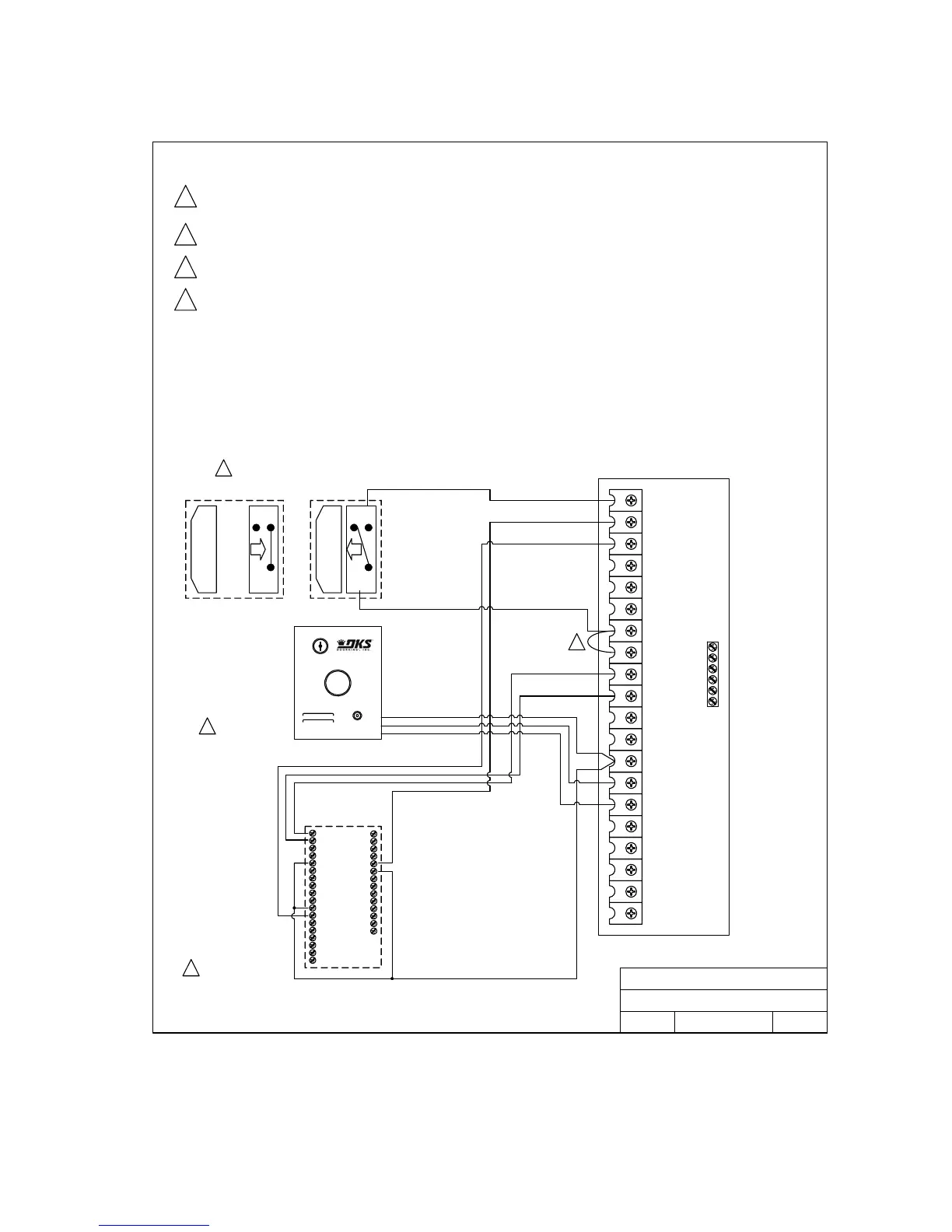
2.4 Auxiliary Device Wiring
123456789101112
4404-010
Circuit Board
Secondary Entrapment
Protection Inputs
DOORKING, INC., INGLEWOOD, CA 90301
Title:
Date: Rev.Dwg. No.
N.O.
N.C.
COM
N.O.
N.C.
COM
Green
Red
White
DoorKing 1404-080
Remote Reset Switch
DoorKing 2351-010
Tracker Expansion Board
Auxiliary Stop Using Magnetic Switch
Normal
Operation
Operator
Stopped
1
2
The auxiliary stop switch will stop a moving gate when activated or will prevent the gate operator from starting when activat ed. Note that
this input is normally open and that a switch closure is required to activate the stop function . Because of this, the auxiliary stop
shown must NEVER be used as a safety interlock device.
Jumper is placed across terminals 7 and 8 ONLY WHEN THE AUXILIARY STOP INPUT IS USED.
The Remote Alarm Reset Station MUST be mounted in the line-of-sight of the gate operator.
Using a 2351-010 Tracker Expansion Board, operator data can be sent to the access controller (DoorKing 1833, 1835, 1837 or 1838 only).
Refer to Installation Manual 2351-065 for detailed information.
1
2
3
4
3
4
11/07
A
4404-AUXDEV-1
Model 9210, 9220, 9230, 9530
Auxiliary Device Wiring Diagram
Open Photo
Close Photo
Open Edge
Close Edge
Common
Common
13 14
15
16 17 18
19 20
2351-010
Circuit Board
1
2
3
4
5
6
7
8
9
10
11
12
13
14
15
16
17
18
1
2
3
4
5
6
7
8
9
10
11
12
13
14
9210-065-H-8-08 Page 29