XTLplus Installation and Programming Guide Digital Monitoring Products
7
INSTALLATION
17.1 Description
The CELL MODULE header is provided to connect a 265C CDMA Cellular Communicator. The 265C provides
an integrated PCB antenna. Refer to the 265C Cellular Communicator Installation Guide (LT-1450) complete
installation information.
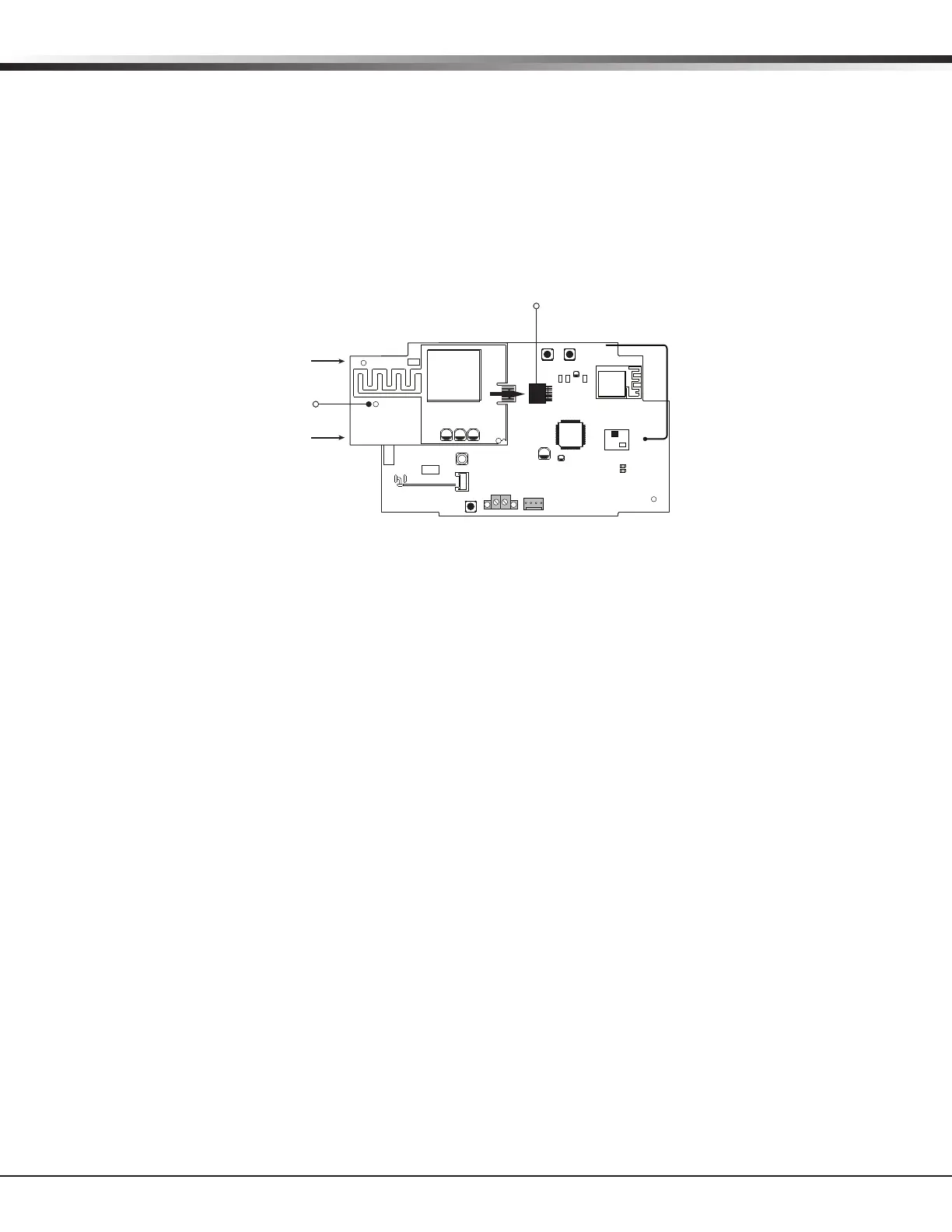
Installing the 265C on the XTLplus:
1. Avoiding a sharp angle and keeping the 265C PCB parallel to the XTLplus PCB, slide the 265C PCB into the
XTLplus 8-pin CELL MODULE connector. Apply even pressure to the end of the 265C PCB to fully seat the
module. See Figure 5.
2. Align the stando hole in the 265C with the stando on the XTLplus PCB and snap in place.
Wireless Keypads
18.1 Mounting Wireless Keypads
DMP Wireless keypads have removable covers that allow the base to be mounted on a wall, desk stand or
other at surface using the screw holes provided on each corner.
Eight-Pin CELL MODULE
Connector
RESETLOAD
BAT
PROG
R B
+ DC -
S
N
LEV
LPC-0181
R1
INSTALL GUIDE
LT-1434
CELL
MODULE
©
2015 DMP
WWW.DMP.COM
LEV
MODEL 265C
Stando
Hole
Figure 5: 265C Installed on the XTLplus