Digital Monitoring Products XTLplus Installation and Programming Guide
40
APPENDIX
Panel Settings
Pressing a select area displays the MAC Address, Serial Number, Frequency Oset, Panel Model, and Firmware
Version.
MAC Address
The MAC address is the panel on-board network hardware address. Press any select area to display the
panel MAC address.
Serial Number
This number is the panel serial number. Reference this number for date-of-manufacture, hardware
version, etc. Press the COMMAND key to view the next option.
Frequency Oset
This menu option displays the frequency oset of the panel.
Panel Model
This menu option displays the panel model number.
Firmware Version
This menu option displays the Firmware Version number of the panel and date it was released.
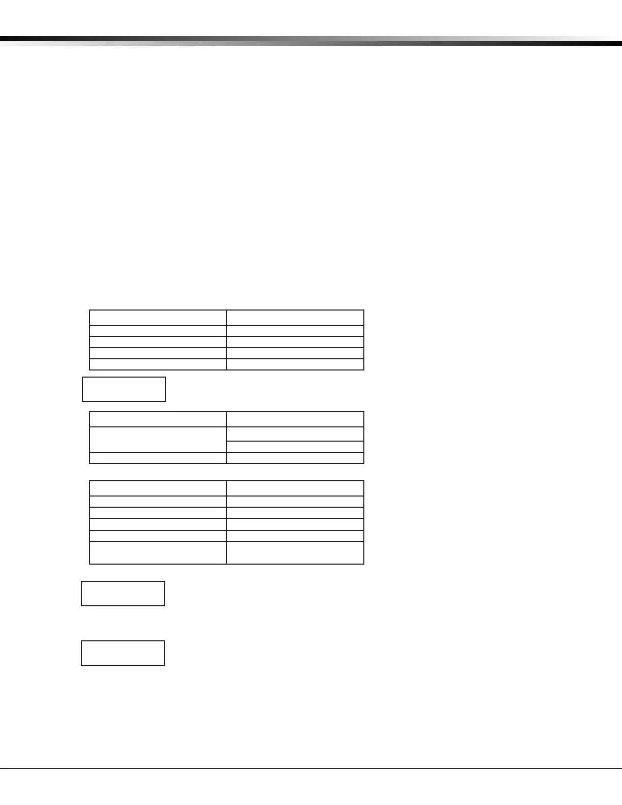
Communication Status
This option tests the individual components of cellular or wireless network communication. The displayed
results are shown below.
Cellular Results:
Successful Display Failure Display
MODEM OPERATING NO MODEM FOUND
IDENTIFIED NO SIM CARD
TOWER DETECTED NO TOWER
REGISTERED NOT REGISTERED
This displays the cellular signal strength of the nearest tower for the SIM card carrier.
The
▐
’s represent the signal strength 0-7. Select YES to continue through the remaining
component tests. Select NO to stop testing and return to the COMM STATUS option.
Successful Display Failure Display
CONNECTED
CONNECT ERROR
NOT ACTIVATED
COMM PATH GOOD NO ACK RECEIVED
Wireless Results:
Successful Display Failure Display
LINK OK LINK ERROR
DHCP OK DHCP ERROR
GATEWAY FOUND NO GATEWAY
DEST FOUND NO DESTINATION
COMM PATH GOOD NOT CONNECTED
NO ACK RECEIVED
Cellular Signal Strength (CELL SIGNAL)
This option provides a way to test the cellular signal strength of the nearest tower
for the cellular carrier. Press any select area to display cell signal strength. The X’s
represent the numerical value of the cell signal strength in -dBm. The
▐
’s represent the
signal strength 0-7.
Cell Roaming Indicator
The Cellular Signal Strength option in the panel’s Diagnostic menu contains a roaming
indicator. When the 265C Cellular Communicator is roaming or not in contact with a
Verizon owned tower, ROAM will be displayed on the top line of the keypad along with
the signal strength. To perform the cellular activation process from a keypad, the 265C MUST be in contact
with a Verizon owned tower. If the cellular communicator is in contact with a tower owned by another
network, ROAM and the signal strength displays, but activation cannot be completed. This feature can be
used as a diagnostic tool to troubleshoot activation issues.
Activate Cell
Note: If the 265C Cellular Communicator has not been previously activated, Automatic Cellular Activation
is performed when the panel powers up or is reset. Activate Cell (discussed below) is only necessary when
Automatic Cellular Activation is not successful and communication was not established.
SIGNAL:▐▐▐▐▐▐▐
CONTINUE?NOYES
-XX dBm
SIGNAL:
▐▐▐▐▐▐▐
ROAM-XXdBm
SIGNAL:
▐▐▐▐▐▐▐