16
• Vise Overlap: Choices are OVERLAP and NO
OVERLAP.
(a) OVERLAP: After the index has moved forward and
the xed vise jaws clamp, a time lapses before the
index vise jaws open. This selection is forced if
“NESTING” is selected in the Vise Control option.
The best accuracy is obtained when “OVERLAP”
is selected because the material is always clamped
by one of the vises.
(b) NO OVERLAP: After the index has moved forward,
the index vise jaws open at the same time as the
xed vise jaws close. This selection allows slightly
faster operation because both vises are cycled at
the same time. This selection also allows material
that has a tendency to “climb” in the vises to fall
back to the vise bed.
Thersttimeuserisadvisedtoselectthe“NO
OVERLAP” setting.
(c) Press the "RIGHT" arrow key to move to Set-up
Screen 2. Use the "UP" and "DOWN" arrows to move
to a set-up parameter, when a eld is highlighted
enter the value, then press the "+/-" key to accept
the change and advance to the next item. Press
ENTER twice or CLEAR to quit.
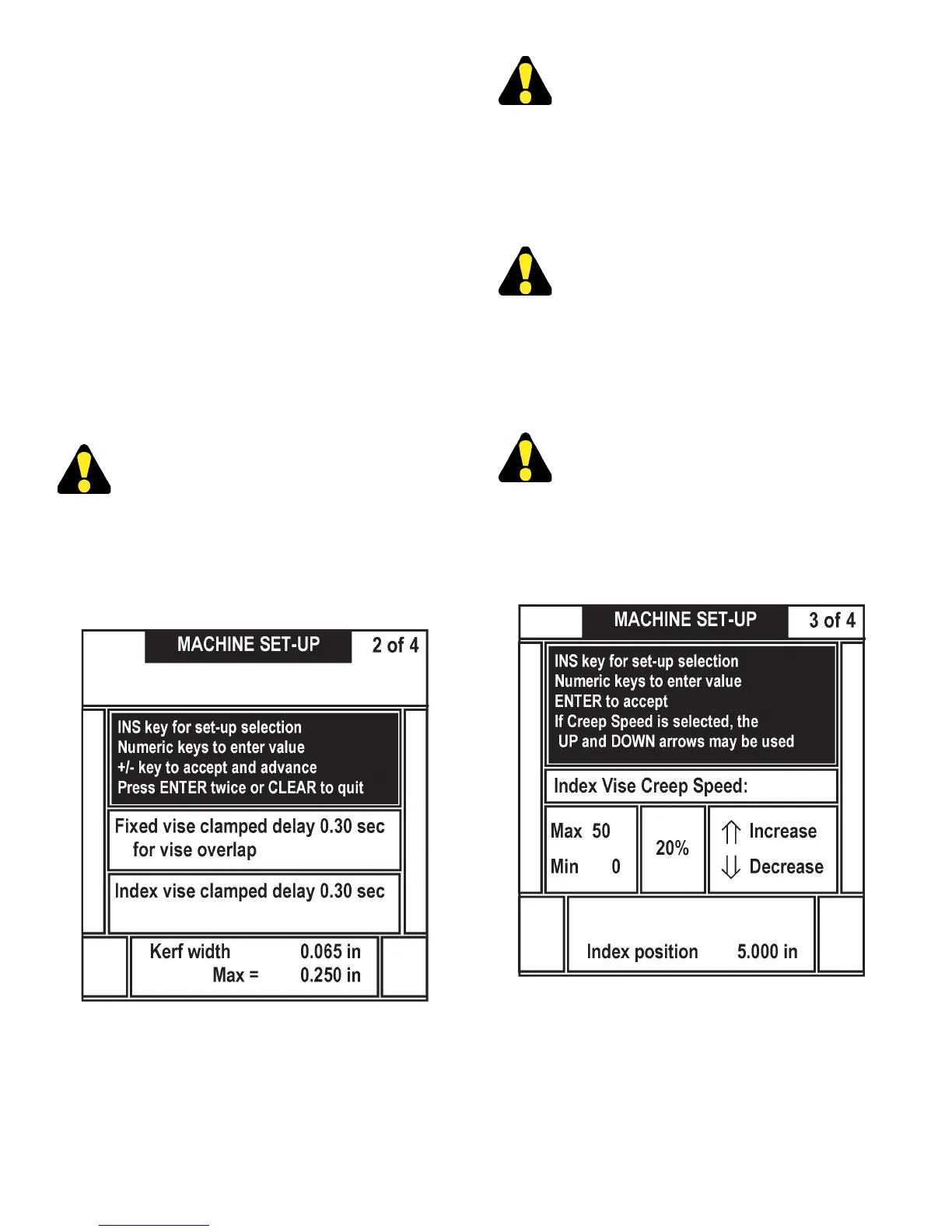
Machine Set-Up Screen Display (2 of 4) (F3).
• Fixed Vise Delay. This allows the operator to set a
time allotted for the xed vise jaws to clamp before
index movement is allowed (due to longer closing
time resulting from variable vise pressure, etc.) and
is used with the nesting xture. Entry range is from
.3 to 9.99 seconds.
A Fixed Vise Delay of .3 seconds is suggested
forthersttimeuser.
• Index Vise Delay. This allows time allotted for the
index vise jaws to clamp before index movement
is allowed (due to longer closing time resulting
from variable vise pressure, etc.) and is used with
the nesting xture. Entry range is from .3 to 9.99
seconds.
An Index Vise Delay of .3 seconds is suggested
forthersttimeuser.
• Kerf Width. Allows the operator to enter the
dimension of the actual kerf width obtained from the
saw band. The saw uses this value to compensate
for the material removed by the cut. For the highest
accuracy the user should measure the actual kerf
width and enter the measured value.
Akerfwidthof.065issuggestedfortherst
time user.
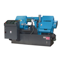
(d) Press the "RIGHT" arrow key to move to Set-up
Screen 3 which shows the Index Vise Creep Speed
control (F16). For description and instructions on
this control, see Creep Speed (F16) later in this
manual.
Machine Set-Up Screen Display (3 of 4) (F3).
Press the right arrow key to move to Set-up screen 4.
• BAND SPEED. Press 0/INS key to select the
Band Speed, enter a new value, press ENTER to
accept. If the Band Speed key is active, then the
"UP/DOWN" arrow keys will increase or decrease
the band speed.
OPERATOR WORKSTATION (Continued....)