3.8. Connection of thermal oil (only for thermal oil models)
The installation of the dryer with thermal oil heating must comply with current standard
regulations.
The customer must connect the thermal oil to the machine to the foreseen connection through a
valve (we recommend a 3-way valve to favour oil circulation in the facility, with a bypass to the
machine when thermal oil supply is not necessary).
The machine supplies a signal of 230V active when an inlet of oil is required.
The measurements of the power supply and evacuation valve must correspond to the adequate,
flow and pressure and temperature according to the machine's specifications. The diameter must
not be smaller than the inlet and outlet flanges of the dryer.
Tumble dryer’s batteries normally work with thermal fluid flows ranging from 7 m
3
/h for the
DTT/DTM-45 and 10 m
3
/h. for the DTT/DTM-60 and DTT/DTM-80, and an inlet temperature of
around 175 ºC.
CAUTION: USE APPROPRIATE COMPONENTS FOR THE FLOW AND TEMPERATURE
WORKED WITH
3.9. Assembly and location of gas, steam, and electric batteries
LOCATION OF HEATER BATTERIES:
The heater batteries are supplied unassembled and are located
inside the machine.
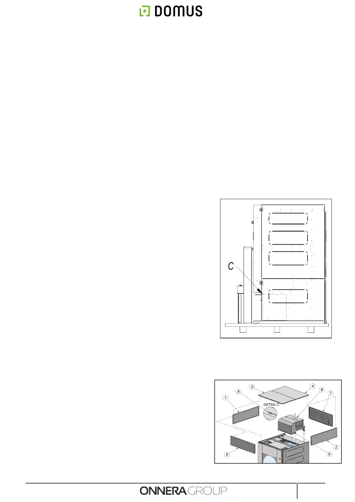
To access the batteries, it is necessary to open the filter box and
remove the lower cover to remove it. This is the case for all
DTT/DTM-60, DTT/DTM-80 dryers and for the DTT/DTM-45 electric
battery (see position C in the diagram).
In the case of the DTT/DTM-80, the filter assembly and the
upper front panel are located inside the drum. In the rest of
the models, it is located on the front of the machine.
Assembly process of batteries:
Note: A plastic bag containing the necessary bolt stock can be found inside the drum. Follow the following
procedures to assemble the batteries depending on the type of heating.
3.9.1. Process for the assembly of the gas battery:
1. Remove ceiling pieces 3 and 4 to access side covers 1 and 2 and
front panel 5 which can be found dismounted inside.
2. Mount battery 6 as shown in the drawing and secure with bolts.
3. Pass the sheath B of the thermostat through the bushing A and
place it with the pre-assembled clamp on the battery (see Fig. 1).
4. Mount side panels 1 and 2 with the M5x10 bolts.
5. Mount front panel 5 and ceiling pieces 3 and 4 with the M5x40
bolts.
6. Replace rear cover 7 using supplied screws.