Vehicle System System Operation 28
Steering Gear
Steering Gear
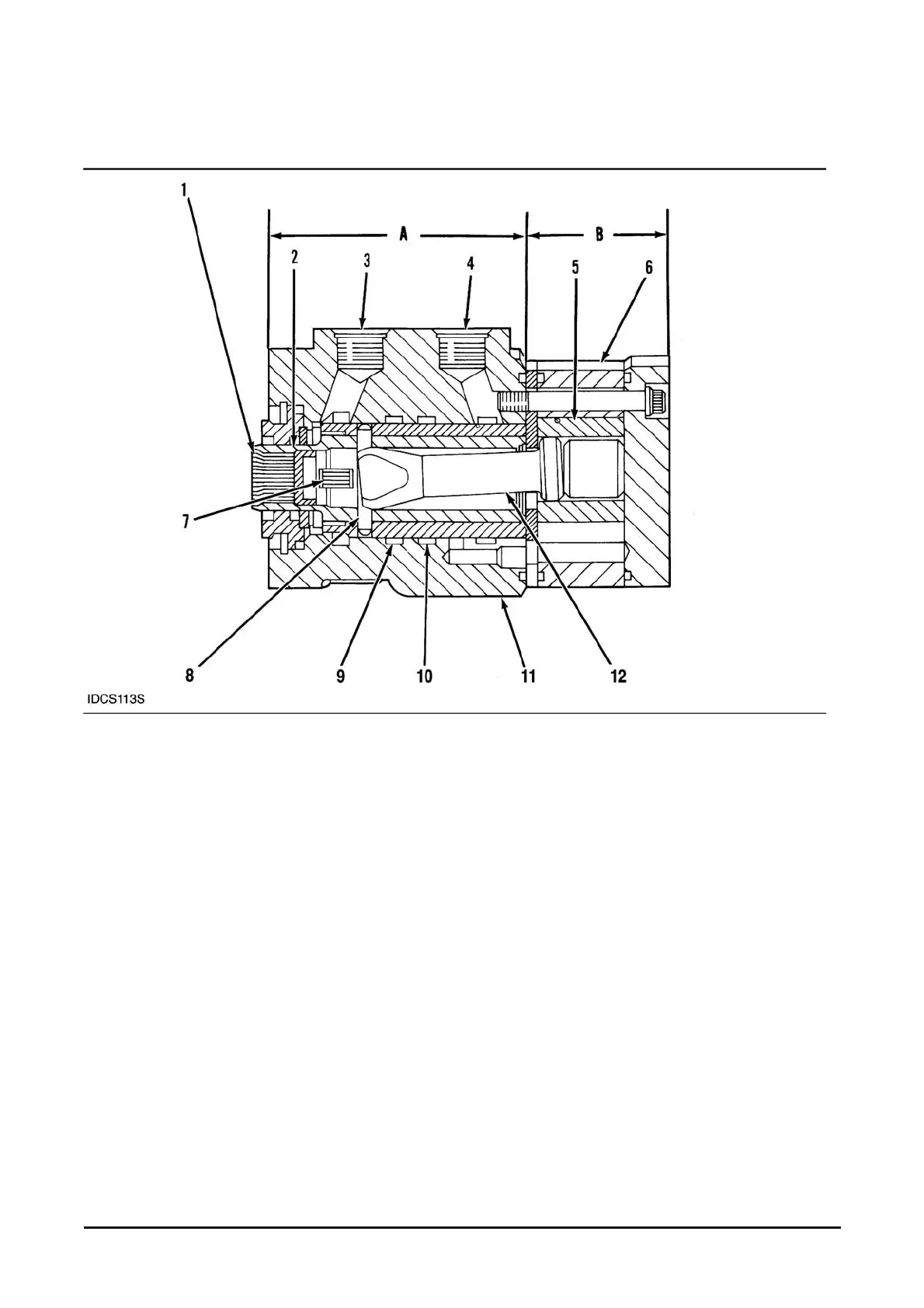
(1) Spool. (2) Sleeve. (3) Outlet (to tank). (4) Inlet (for pump oil). (5) Internal pump gear. (6) External pump gear. (7) Centering springs. (8)
Pin. (9) Left turn port. (10) Right turn port. (11) Body. (12) Drive. (A) Control section. (B) Metering section.
Lift trucks use the non load sensing, open center (oil
flow to steering gear only when needed) steering
gear.
All lift truck hydraulic lines serve a dual purpose in
that they serve both the steering and cylinder
hydraulics through the use of a priority valve. The
priority valve sends oil to the steering gear before
the needs of the cylinder hydraulics are met.
The steering gear has two main sections: control
section (A), and pump or metering section (B).
These two sections work together to send oil to the
steering cylinder.
Oil from the priority valve goes through inlet (4) into
the control section of the steering gear. When the
steering wheel is turned, the control section sends
the oil to and from the metering section and also to
and from the steering cylinder.
The metering section is a small hydraulic pump. It
controls (meters) the oil that goes to the steering
cylinder. As the steering wheel is turned faster, there
is an increase in the flow of oil to the steering
cylinder. This increased flow causes the main valves
pool to move farther. As the spool moves farther,
more oil can flow from the priority valve or power
steering pump to the steering cylinder, and a faster
turn is made.