Vehicle System Testing and Adjusting 41
Hydraulic System
Relief Valve Pressure Check
CONTROL VALVE
ITEM psi kPa bar
Kgf/
㎠
EU
USA
LIFT
TILT
(2630
±35)
18100
±250
(181±
2.5)
(185±
2.5)
2.0t
NON EU
NON
USA
LIFT
TILT
(3130
±35)
21550
±250
(216±
2.5)
(220±
2.5)
EU
USA
LIFT
TILT
(2840
±35)
19500
±250
(195±
2.5)
(199±
2.5)
2.5t
NON EU
NON
USA
LIFT
TILT
(3130
±35)
21550
±250
(216±
2.5)
(220±
2.5)
EU
USA
LIFT
TILT
(3130
±35)
21550
±250
(216±
2.5)
(220±
2.5)
3.0t
NON EU
NON
USA
LIFT
TILT
(3130
±35)
21550
±250
(216±
2.5)
(220±
2.5)
ALL ALL Aux
(2040
±35)
14000
±250
(140±
2.5)
(143±
2.5)
Use the Fittings Group to check the relief valve
pressure.
WARNING
Hydraulic oil, under pressure can remain in the
hydraulic system after the engine and pump
have been stopped. Personal injury can be
caused if this pressure is not released before
any work is done on the hydraulic system. To
prevent possible injury, lower the carriage to the
ground, turn the engine off and move the control
levers to make sure all hydraulic pressure is
released before any fitting, plug, hose or
component is loosened, tightened removed or
adjusted. Always move the lift truck to a clean
and level location away from the travel of other
machines. Be sure that other personnel are not
near the machine when the engine is running
and tests or adjustments are made.
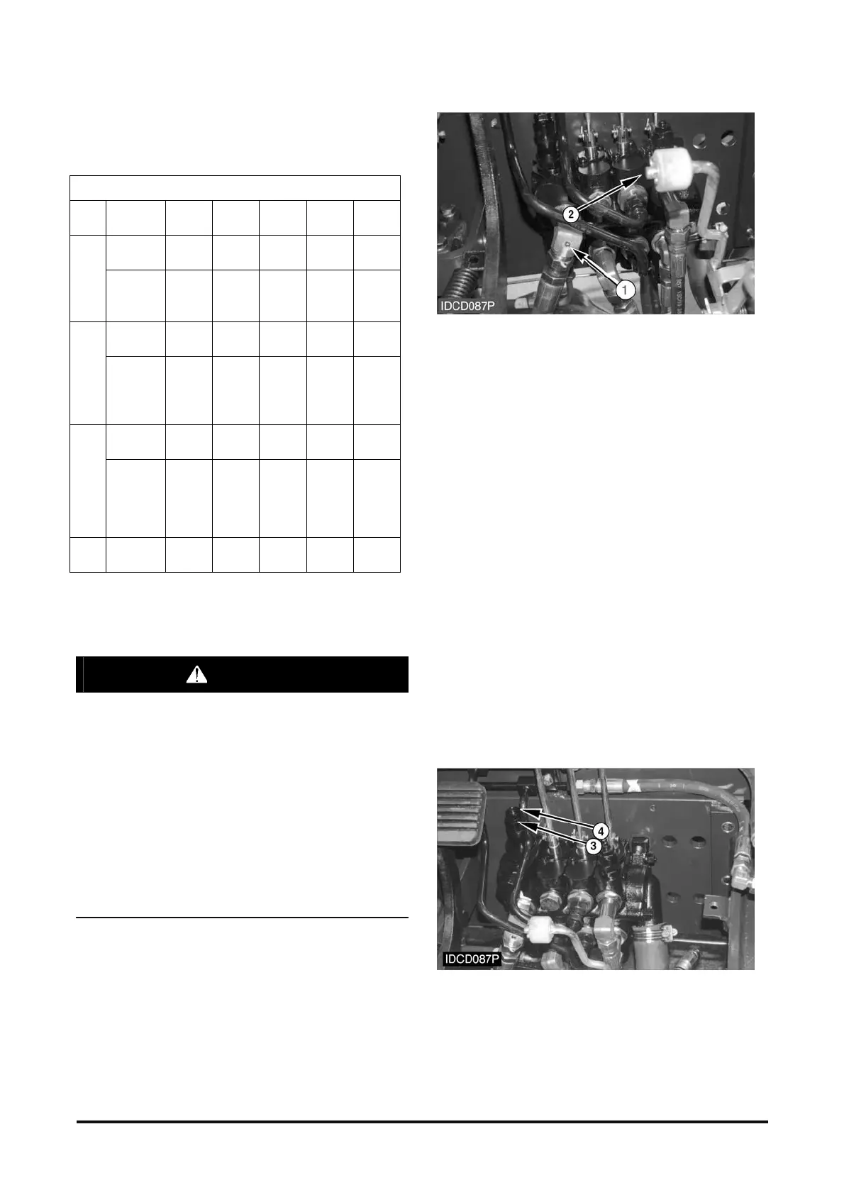
Pressure Tap Location
(1) Pressure tap.
With the engine off, remove cap (1) from nipple
assembly (2) and connect the 28,000 kPa (4000 psi)
gauge to the nipple assembly.
Lift Relief Valve Check and Adjustment
1. Start the engine and activate the hydraulics until
the hydraulic oil is at the normal operating
temperature.
2. Lift mast to maximum fork height without load on
forks. Increase engine rpm to high idle. Hold the
lift control lever in the lifting position and watch the
gauge. The gauge indication is the pressure that
opens the relief valve at the end of lift cylinder
stroke.
Caution : Make sure there is adequate ceiling
height. Lift cylinder must be fully extended. Mast
should be in the vertical position and truck parked
on level ground.
3. The correct pressure setting is shown in the chart.
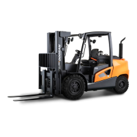
Relief Valve Adjustment.
(3) Lock Nut. (4) Stud.