SP002028Swing Reduction Gear
Page 48
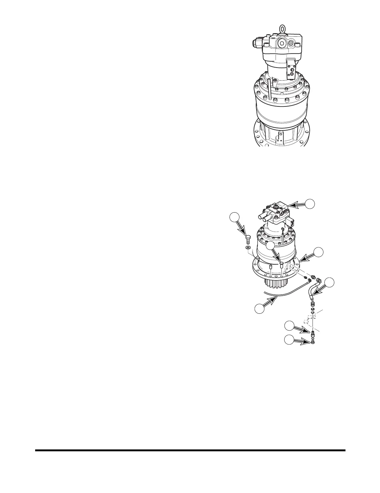
INSTALLATION
1. Coat pinion gear with grease. Refer to operation manual
for specifications.
2. Make sure two alignment pins (6, Figure 129) are installed
in flange of swing reduction gearbox (5).
3. Using a suitable lifting device, sling swing motor (1, Figure
129) and position swing motor and reduction gearbox (5)
as an assembly on unit.
4. Install twelve bolts and washers (4, Figure 129) to secure
swing reduction gearbox (5) to frame.
NOTE: Apply Loctite #262 to bolt threads.
NOTE: Tighten bolt to 95 kg•m (690 ft lb).
5. Connect hose (2, Figure 129) to reduction gearbox (5).
6. Connect grease lubrication line (7, Figure 129) to reduction
gearbox (5).
7. Connect hoses as tagged during removal to swing motor
(1, Figure 129).
8. Fill swing reduction gearbox with oil. Refer to operation
manual for specifications.
FG000982
Figure 128
1
4
6
5
7
2
3
8
FG004063
Figure 129