SP000068
Page 7
Axial Piston Pump
Theory of Operation
Construction
This pump assembly consists of two pumps connected by a
spline inside 1st gear (116). The two pumps can be driven
simultaneously as the rotation of the prime mover (engine) is
transferred by the drive shaft (F) (111) on the front side. The
suction and discharge ports are integrated at the connecting part
of the two pumps; i.e. in valve block (312): The suction port
serves both the front pump and the rear pump.
Function
The pumps may be classified roughly into the rotary group
performing a rotary motion and working as the major part of the
whole pump function: the swash plate group that varies the
delivery rates: and the valve cover group that changes over oil
suction and discharge.
1. Rotary Group
The rotary group consists of a drive shaft (F) (111),
cylinder block (141), piston shoes (151, 152), set plate
(153), spherical bushing (156) and cylinder spring (157).
The drive shaft is supported by bearings (123 and 124) at
both ends. The shoe is caulked to the piston to form a
spherical coupling. It has a pocket to relieve thrust force
generated by loading pressure and to take hydraulic
balance so that it slides lightly over the shoe plate (211).
The subgroup is composed of a piston and shoe pressed
against the shoe plate by the action of the cylinder spring
via a retainer and a spherical bush.
Similarly, the cylinder block is pressed against valve plate
(313) by the action of the cylinder spring.
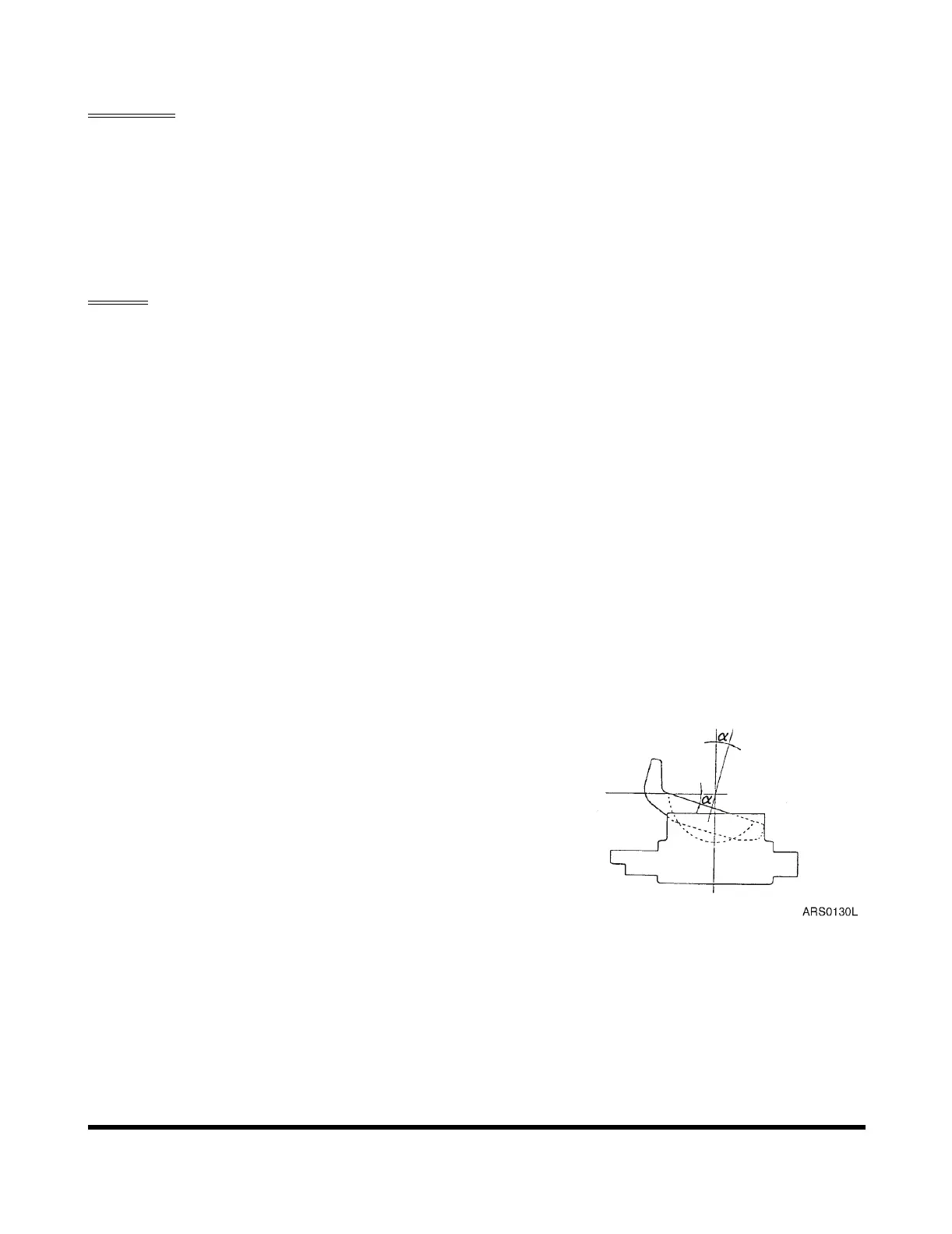
2. Swash Plate Group
The swash plate group consists of swash plate (212), shoe
plate (211), swash plate support (251), tilting bushing
(214), tilting pin (531) and servo piston (532).
The swash plate is a cylindrical part formed on the
opposite side of the sliding surface of the shoe and is
supported by the swash support.
The servo piston moves to the right and left as hydraulic
oil, controlled by the regulator is transmitted to each
hydraulic chamber on both ends of the servo piston. The
swash plate slides over the swash plate support via the
spherical part of the tilting pin to change the tilting angle
(α).
Figure 2 SWASH PLATE GROUP