SP001751Hydraulic System Troubleshooting, Testing and Adjustment
Page 10
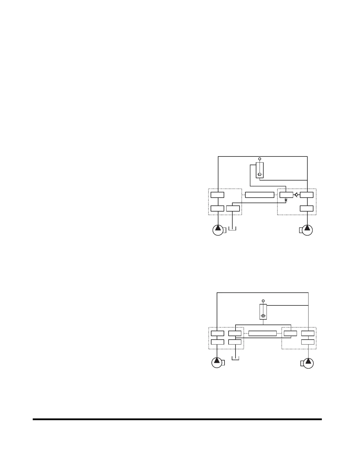
Arm Operating Circuit
The arm operating circuit includes both the right and left
hydraulic main pumps, the right and left halves of the control
valve, a slow return orifice, and the arm cylinder. The circuit can
be operated in the two-stage speed control mode which works
through both halves of the control valve and doubles the volume
of oil flowing to the cylinder.
Overload relief valves set at 360 kg/cm
2
(5,112 psi) have been
installed at the AM 1 and AMD 1 ports on the right side of the
control valve to protect the circuit and system components from
possible damage caused by shocks and/or overload pressure.
Additional protection - to prevent cavitation of the cylinder - is
provided by a makeup valve and reservoir return circuit, which
ensures that the volume of oil going to the cylinder will not
exceed the volume of oil coming out.
Arm Crowd Circuit
When the arm control lever is put in the crowd mode, the left
side pilot valve generates secondary pressure that is transmitted
to the AM1 and AM2 spools of the control valve simultaneously.
When secondary pilot pressure reaches 7 - 9 kg/cm
2
(100 - 130
psi), the arm control valve spools AM1 and AM2 open. Output
flow from both halves of the pump assembly is directed to the
arm cylinder.
When working in the arm crowd mode, under certain conditions,
oil in the arm cylinder could suddenly be forced out by the weight
of the arm and bucket. Insufficient oil flow to the cylinder could
lead to cavitation in the cylinder and/or surging or irregular
movement. This is prevented by a regeneration valve attached
to the control valve which maintains the balance between oil
flowing into the cylinder and oil flowing out.
Arm Dump Circuit
When the arm control lever is put in "dump" mode, the left side
pilot valve generates secondary pilot pressure that goes to both
spools AM1 and AM2 of the control valve simultaneously.
When pilot pressure reaches 7 - 9 kg/cm
2
(100 - 130 psi), the
control spools open, allowing oil from PUMP (L) and PUMP (R)
to flow to the arm cylinder.
PUMP(L) PUMP(R)
PL PRTL
CONTROL
VALVE(L)
ARM
CYLINDER
CONTROL
VALVE(R)
AMD1 AM1
REGENERATION VALVE
AM2
ARS1580L
PILOT VALVE
Figure 4
PUMP(L)
PUMP(R)
TL
PR
AM2
PL
CONTROL
VALVE(L)
ARM
CYLINDER
CONTROL
VALVE(R)
AMD1
ARS1590L
AMD2
PILOT VALVE
AM1
Figure 5
 Loading...