9
ED100/ED250 02-2018DL4614-050
dormakaba ED100/ED250 Service Manual Chapter 7
Terminal board accessory interfaces
. ED/ED terminal board accessory interfaces
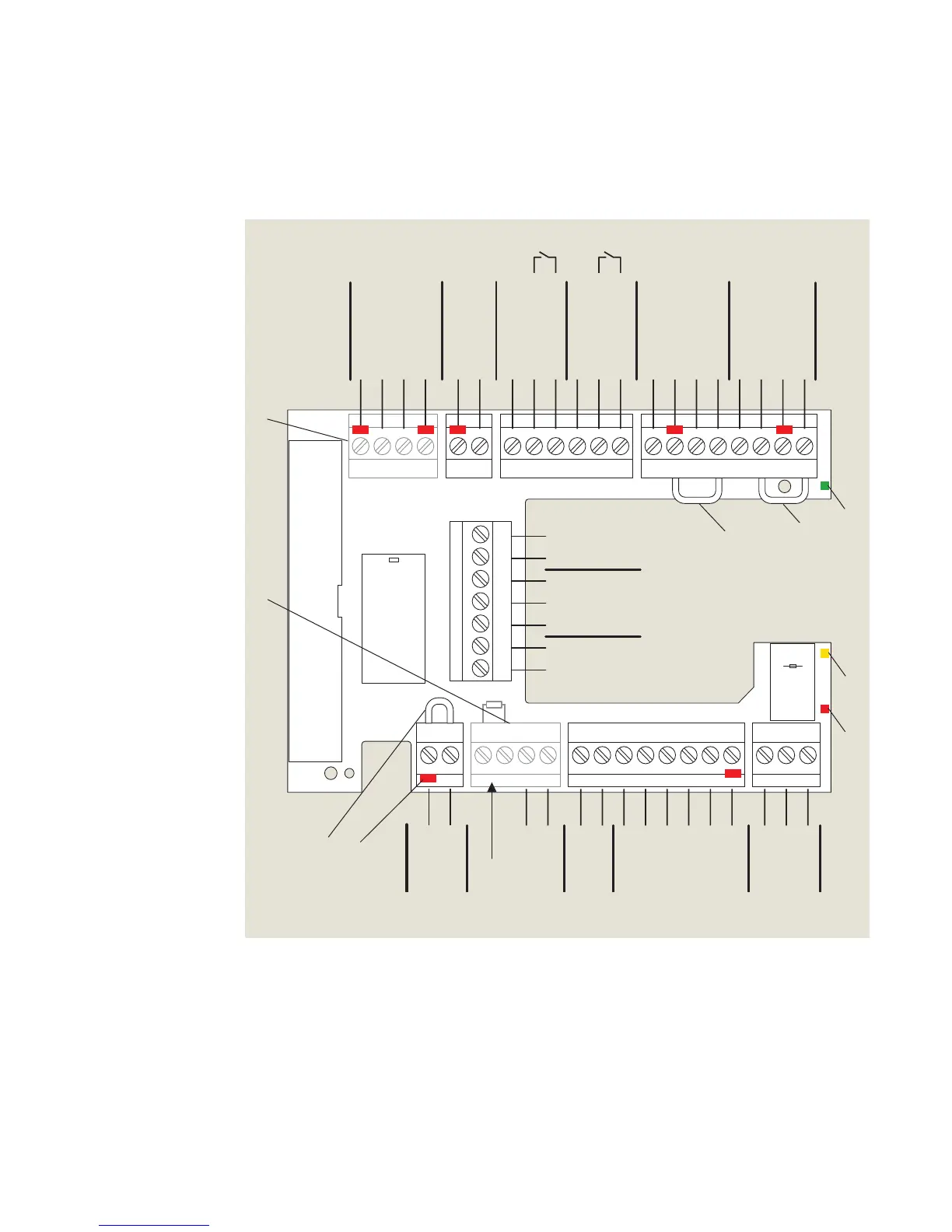
Fig. 7.1.1 Terminal board electrical connections
1 Green LED (Para. 6.4)
2 Yellow LED (Para. 6.4)
3 Red LED (Para. 6.4)
4 Key (red insert)
location in socket.
Assigned plug has tab
broken off in same
location.
5 Jumpers, factory
installed at following
terminals:
• and a
• and *
• and *
* Remove jumpers if
safety sensors
installed.
6 DCW® upgrade card
plug included in scope
of delivery.
7 Fire protection upgrade
card plug included in
scope of delivery.
(v.)
Night-bank,
K resistor
not required
97 98 99 30 31 32 34 33 3335
1
36
1
4
4a
3
BA
1
57 57a
142
3
141
3
1
15
17
3
111
13 3
43 3646362
1G
3
+ 24 V
Signal input
0 V
ial Open
nt Open
xit Only
Off
N.C.
COM
Test output
X5X4
X3
X6 X9 X1 X7
+ 24 V
X8
0 V
X10
8 - 24 AC/DC
+ 5% Wet
DCW bus
Swing side
Approach side
Safety sensors
Activation inputs
Interior Exterior
Night-
bank
input
+ 24 V
Signal input
0 V
+ 24 V
+ 24 V
Signal input
Signal input
0 V
0 V
Test output
0 V
24 V
Maximum current
load: 1.5 A
Output
COM
N.O.
N.C.
0 V
Locking relay
Maximum current:
1A, 48 V DC/AC
Locking feedback contact
0 V
0 V
+ 24 V
0 V
0 V
N.O.
Smoke
detectors
Emergency
close
Night
trigger
Program, exit only
switches
Door status
24 VDC
Class II
1
2
3
4
5
6
7
5
5
Reference Note 1
Note 1: Terminals 3 and 43 also used for
swing side overhead presence sensor
input when Parameter ST is set to 7 or 8.
Reference Chapter 15, Parameters.
 Loading...