WH
GY
RD
BN
BU
PK
8
7
BU
BN
RD
GY
WH
PK
1
2
3
4
5
6
7
8
9
10
11
12
13
14
15
16
17
18
19
20
21
22
23
24
25
26
27
28
29
30
31
32
33
34
35
36
37
38
6
5
4
3
2
1
WH
GY
RD
BN
BU
PK
8
7
BU
BN
RD
GY
WH
PK
1
2
3
4
5
6
7
8
9
10
11
12
13
14
15
16
17
18
19
20
21
22
23
24
25
26
27
28
29
30
31
32
33
34
35
36
37
38
6
5
4
3
2
1
DORMA
3
DORMA
ES 200
—
WH
GY
RD
BN
BU
PK
8
7
BU
BN
RD
GY
WH
PK
1
2
3
4
5
6
7
8
9
10
11
12
13
14
15
16
17
18
19
20
21
22
23
24
25
26
27
28
29
30
31
32
33
34
35
36
37
38
6
5
4
3
2
1
DORMA
3
DORMA
ES 200
—
ES 200
51
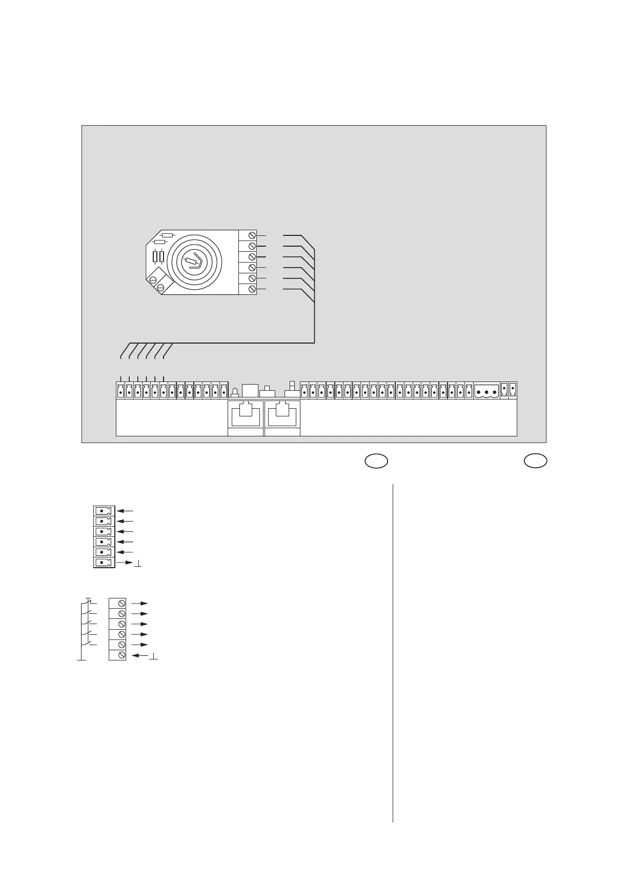
Anschlußplan mechanischer Programmschalter
Wiring diagram mechanical Program switch
Beschreibung und
Klemmendefinition
DE
Steuerung
Description and
terminal connections
EN
Control system
1 AUS OFF
2 AUTOMATIC AUTOMATIC
3 AUSGANG EXIT ONLY
4 TEILOFFEN PARTIAL OPENING
5 DAUERAUF PERMANENT OPEN
6 GND
Programmschalter Program switch
6 AUS OFF
5 AUTOMATIC AUTOMATIC
4 AUSGANG EXIT ONLY
3 DAUERAUF PERMANENT OPEN
2 TEILOFFEN PARTIAL OPENING
1 GND
Steuerung ES 200 Grundmodul
Control system ES 200 Basic module
Programmschalter
Program switch