1
2
3
4
5
6
7
8
9
10
11
12
13
20
25
30
31
32
33
34
35
36
37
38
14
15
16
17
18
19
21
22
23
24
26
27
28
29
WH
YE
GN
BN
PK
GY
RD
BU
WH
YE
GN
BN
PK
GY
RD
BU
IR
BN
WH
IR
GN
YE
WH
GN
YE
BN
PK
RD
BU
GY
PK
RD
BU
GY
1
2
3
4
5
6
7
8
9
10
11
12
13
20
25
30
31
32
33
34
35
36
37
38
14
15
16
17
18
19
21
22
23
24
26
27
28
29
WH
YE
GN
BN
PK
GY
RD
BU
WH
YE
GN
BN
PK
GY
RD
BU
IR
BN
WH
IR
GN
YE
WH
GN
YE
BN
PK
RD
BU
GY
PK
RD
BU
GY
ES 200
—
ES 200
54
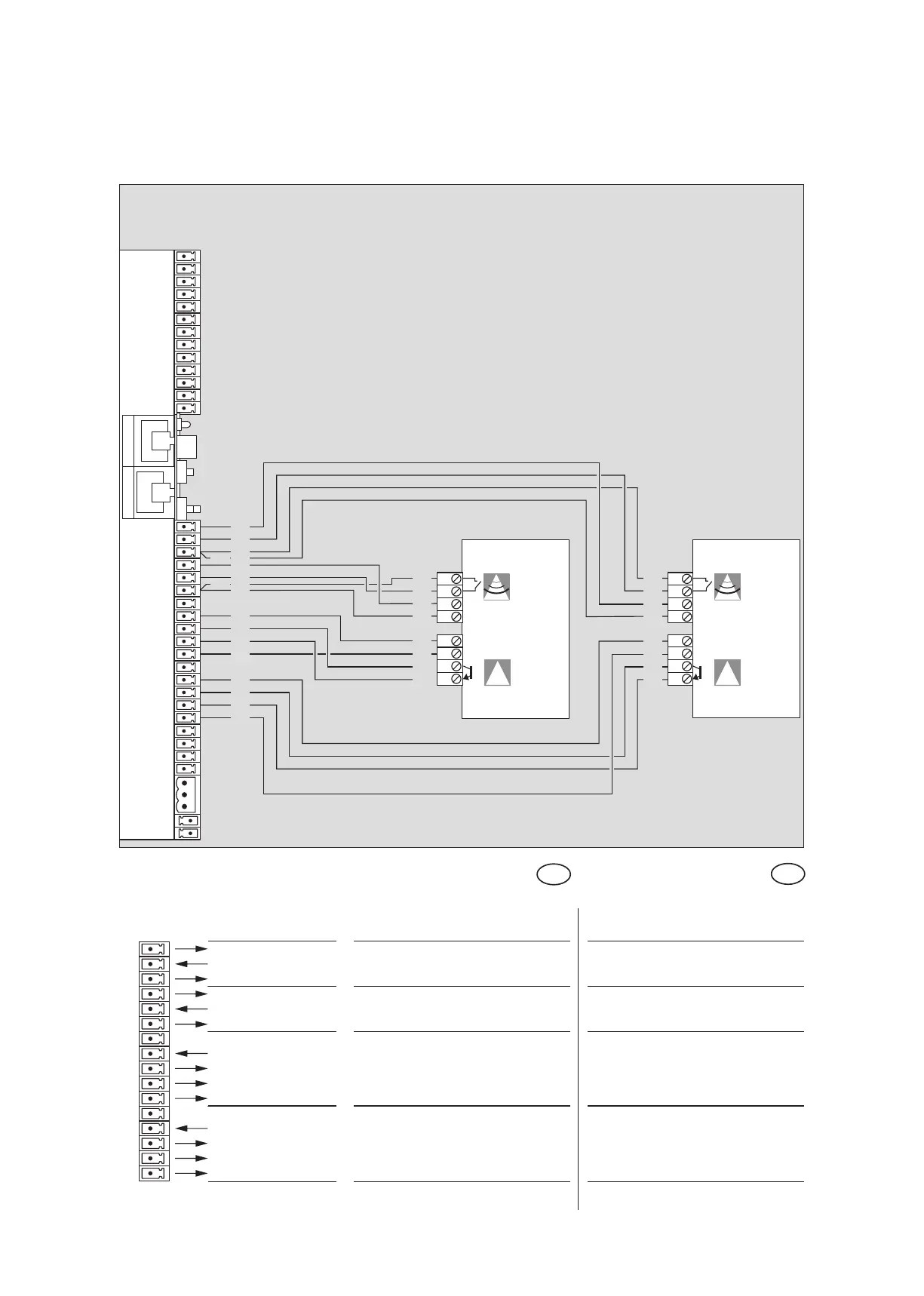
Anschlußplan Melder Activ 8.1, 8.2 und 8.1ON, 8.2 ON
Wiring diagram radar Activ 8.1, 8.2 and 8.1ON, 8.2 ON
Beschreibung und
Klemmendefinition
DE
Steuerung
Description and
terminal connections
EN
Control system
14
15 +27 V DC Radar Außenmelder Radar outside
16 GND
17
18 Radar Innenmelder Radar inside
19 GND
20 +27 V DC
21 LE2 (NPN) Infrarot Präsenzsensor Innen Infrared presence sensor inside
22 +27 V DC
23 LS2 (GND)
24 GND
25 +27 V DC
26 LE1 (NPN) Infrarot Präsenzsensor Außen Infrared presence sensor outside
27 +27 V DC
28 LS1 (GND)
29 GND
Steuerung ES 200 Grundmodul
Control system ES 200 Basic module
Außenmelder
Radar outside
Innenmelder
Radar inside
Bewegungsmelder
Motion detector
27 V/DC
Bewegungsmelder
Motion detector
27 V/DC
Präsenzsensor
Presence sensor
Präsenzsensor
Presence sensor
Anwesenheitsmelder
Presence sensor
Anwesenheitsmelder
Presence sensor