29 28 27 26
25 24 23 22
1
2
3
4
5
6
11
16
7
8
9
10
12
13
14
15
17
18
19
20
IR
IR
RD
BN
PK
WH
RD
BN
PK
WH
IR
WH
PK
BN
RD
29 28 27 26
2 1 25 24 23 22
1
2
3
4
5
6
11
16
7
8
9
10
12
13
14
15
17
18
19
20
IR
IR
RD
BN
PK
WH
RD
BN
PK
WH
IR
WH
PK
BN
RD
ES 200
58
Einstellung am PDA erforderlich
setting on the PDA required
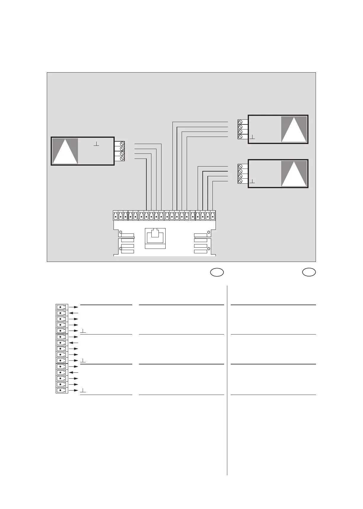
Beschreibung und
Klemmendefinition
DE
Steuerung
Digitale Eingänge
Description and
terminal connections
EN
Control system
Digital input
6 +27 V DC Hauptschließkante Main closing edge
7 Sensoreingang Sensor input
8 +27 V DC
9 Testausgang Test output
10 GND
11 +27 V DC Nebenschließkante 2 Secondary closing edge 2
12 Sensoreingang Sensor input
13 +27 V DC
14 Testausgang Test output
15 GND
16 +27 V DC Nebenschließkante 1 Secondary closing edge 1
17 Sensoreingang Sensor input
18 +27 V DC
19 Testausgang Test output
20 GND
Nebenschließkante 2
Secondary closing edge 2
Hauptschließkante
Main closing edge
ES 200 Funktionsmodul
ES 200 Function module
Nebenschließkante 1
Secondary closing edge 1
DIN 18650
Ausgang AIR
+ 27 V DC
Testeingang
GND
GND
Testeingang
+ 27 V DC
Ausgang AIR
Ausgang AIR
+ 27 V DC
Testeingang
GND
Anschlußplan Schließkantenabsicherung mit Jupiter Presence
Wiring diagram closing edge protection with Jupiter Presence
IR-Präsenzsensoren
Infrared sensors