IR
IR
29 28 27 26
25 24 23 22
1
2
3
4
5
6
11
16
7
8
9
10
12
13
14
15
17
18
19
20
IR
IR
IR
29 28 27 26
2 1 25 24 23 22
1
2
3
4
5
6
11
16
7
8
9
10
12
13
14
15
17
18
19
20
IR
ES 200
57
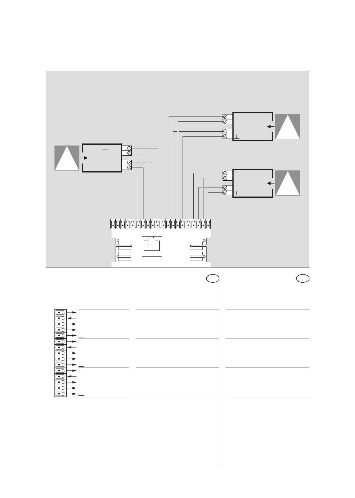
Anschlußplan getestete Schließkantenabsicherung
Wiring diagram tested closing edge protection
Einstellung am PDA erforderlich
setting on the PDA required
Beschreibung und
Klemmendefinition
DE
Steuerung
Digitale Eingänge
Description and
terminal connections
EN
Control system
Digital input
6 +27 V DC Hauptschließkante Main closing edge
7 Sensoreingang Sensor input
8 +27 V DC
9 Testausgang Test output
10 GND
11 +27 V DC Nebenschließkante 2 Secondary closing edge 2
12 Sensoreingang Sensor input
13 +27 V DC
14 Testausgang Test output
15 GND
16 +27 V DC Nebenschließkante 1 Secondary closing edge 1
17 Sensoreingang Sensor input
18 +27 V DC
19 Testausgang Test output
20 GND
IR-Präsenzsensoren
Infrared sensors
Nebenschließkante 2
Secondary closing edge 2
Hauptschließkante
Main closing edge
ES 200 Funktionsmodul
ES 200 Function module
Nebenschließkante 1
Secondary closing edge 1
DIN 18650
Sensorausgang
Testeingang
+ 27 V DC
GND
Sensorausgang
Testeingang
+ 27 V DC
GND
GND
+ 27 V DC
Testeingang
Sensorausgang