IR
IR
IR
25 24 23 22
OFF
ON
2 1 29 28 27 26
21
20
11
10
9
8
7
6
5
4
3
2
1
19
18
17
16
15
14
13
12
1 2
ON
WN , 056710 45532 1´2/12
ES 200
—
IR
IR
IR
25 24 23 22
OFF
ON
2 1 29 28 27 26
21
20
11
10
9
8
7
6
5
4
3
2
1
19
18
17
16
15
14
13
12
1 2
ON
WN , 056710 45532 1´2/12
ES 200
—
IR
IR
IR
25 24 23 22
OFF
ON
2 1 29 28 27 26
21
20
11
10
9
8
7
6
5
4
3
2
1
19
18
17
16
15
14
13
12
1 2
ON
WN , 056710 45532 1´2/12
ES 200
—
ES 200
56
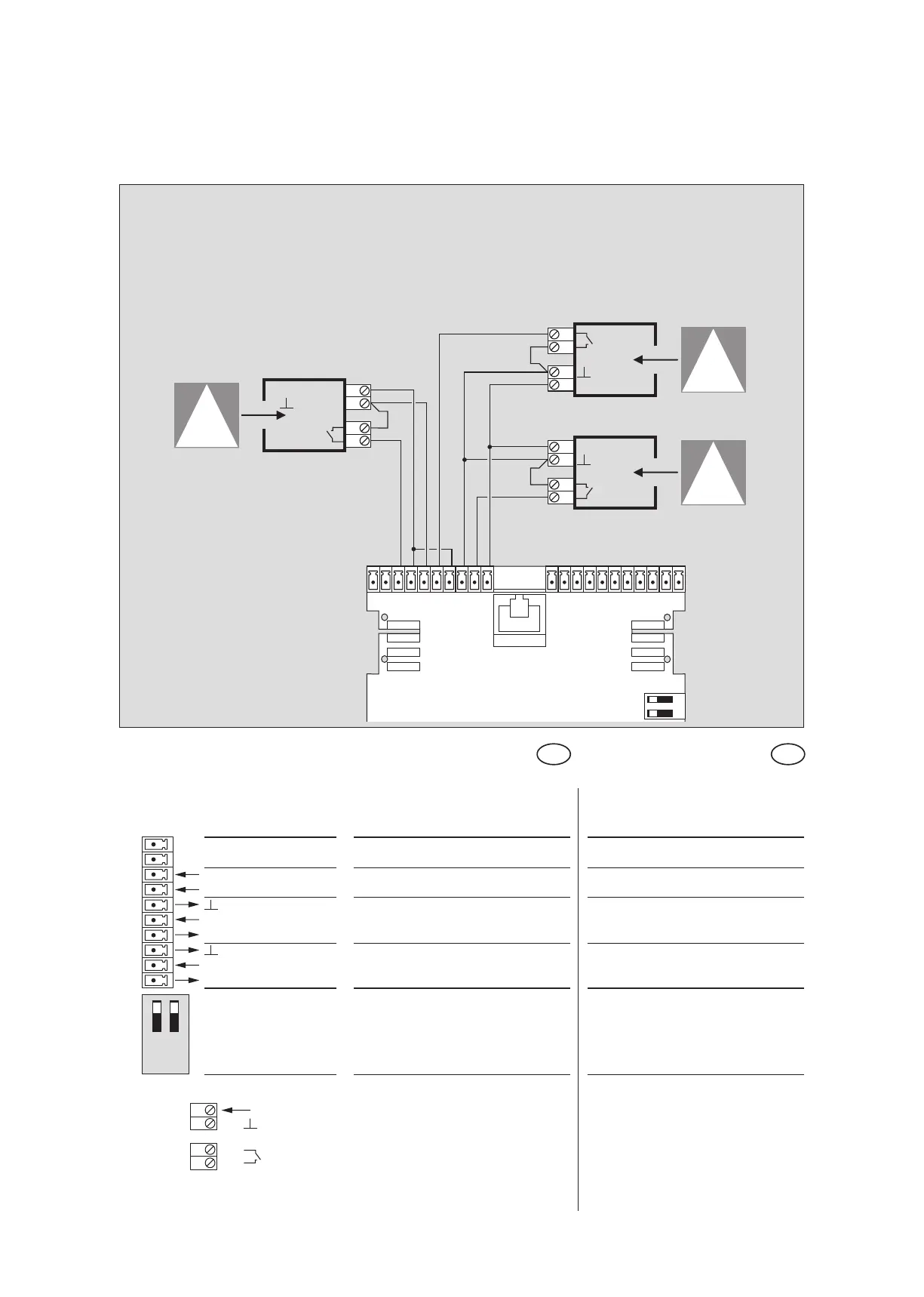
Anschlußplan Schließkantenabsicherung
Wiring diagram closing edge protection
Keine Einstellung am PDA erforderlich
no setting on the PDA required
Beschreibung und
Klemmendefinition
DE
Steuerung
Digitale Eingänge
Description and
terminal connections
EN
Control system
Digital input
IR-Präsenzsensoren
Infrared sensors
Nebenschließkante 2
Secondary closing edge 2
Hauptschließkante
Main closing edge
Nebenschließkante 1
Secondary closing edge 1
ES 200 Funktionsmodul
ES 200 Function module
GND
+ 27 V DC
+ 27 V DC
GND
+ 27 V DC
GND
+
-
+
-
IN 4
IN 3 Hauptschließkante Main closing edge
IN 2 Nebenschließkante 2 Secondary closing edge 2
IN 1 Nebenschließkante 1 Secondary closing edge 1
DCW Adresse 48 DCW Adresse 48
IR-Präsenzsensoren Infrared sensors
21
20
19 IN -
18 IN +
17 GND
16 IN -
15 +27 V DC
14 GND
13 IN -
12 +27 V DC
+ 27 V DC
GND