GN
YE
WH
BN
WH
GN
YE
BN
22 23 24 25
ON
OFF
26 27 28 29 1 2
25 24 23 22
OFF
ON
2 1 29 28 27 26
21
20
16
14
13
12
11
10
9
8
7
6
3
2
1
19
18
17
15
5
4
1
2
3
6
7
8
9
10
11
12
13
14
16
20
21
4
5
15
17
18
19
GN
YE
WH
BN
WH
GN
YE
BN
22 23 24 25
ON
OFF
26 27 28 29 1 2
25 24 23 22
OFF
ON
2 1 29 28 27 26
21
20
16
14
13
12
11
10
9
8
7
6
3
2
1
19
18
17
15
5
4
1
2
3
6
7
8
9
10
11
12
13
14
16
20
21
4
5
15
17
18
19
GN
YE
WH
BN
WH
GN
YE
BN
22 23 24 25
ON
OFF
26 27 28 29 1 2
25 24 23 22
OFF
ON
2 1 29 28 27 26
21
20
16
14
13
12
11
10
9
8
7
6
3
2
1
19
18
17
15
5
4
1
2
3
6
7
8
9
10
11
12
13
14
16
20
21
4
5
15
17
18
19
WH
BN
GN
YE
WH
BN
GN
YE
22 23 24 25
ON
OFF
26 27 28 29 1 2
1
2
3
4
5
6
9
10
11
12
15
16
17
18
19
20
21
7
8
13
14
25 24 23 22
OFF
ON
2 1 29 28 27 26
21
20
19
18
17
16
15
12
11
10
9
6
5
4
3
2
1
14
13
8
7
1 2
ON
ES 200
64
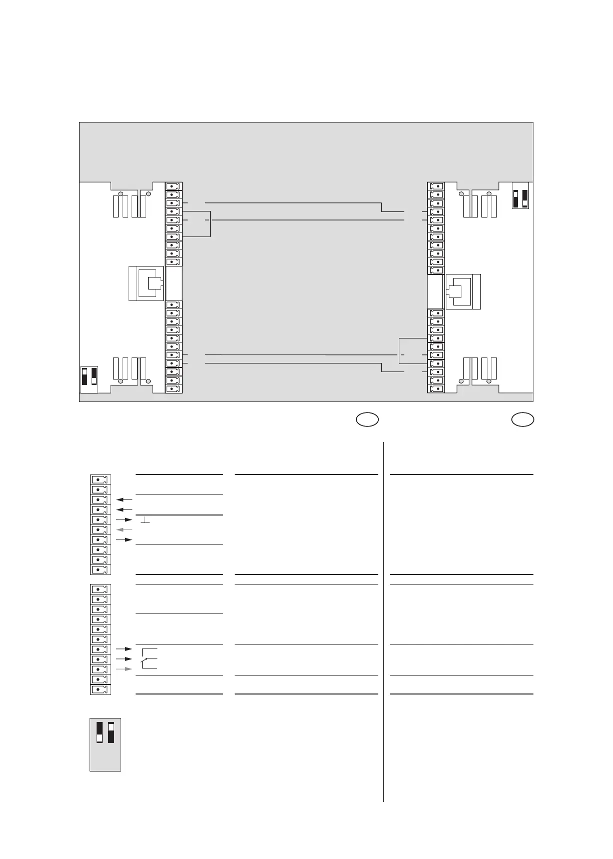
Anschlußplan Schleuse
Wiring diagram lock
TÜR A ES 200 Funktionsmodul
DOOR A ES 200 function module
Keine Einstellung am PDA erforderlich
no setting at the PDA required
TÜR B ES 200 Funktionsmodul
DOOR B ES 200 function module
21
20
19 IN -
18 IN +
17 GND
16 IN
15 +27 V DC
14
13
12
11
10
9
8
7
6
5 NO
4 C
3 NC
2
1
IN 4
IN 3 Schleuse sperren Lock disabled
(Eigene Tür wird gesperrt) (own door is blocked out)
OUT 1
IN 2
OUT 4
IN 1
OUT 2 Schleuse sperren Lock disabled
(Andere Tür wird gesperrt) (other door is blocked out)
OUT 3
Digitale Ausgänge Digital output
Beschreibung und
Klemmendefinition
DE
Tür A und B: Steuerung
Digitale Eingänge
Description and
terminal connections
EN
Door A and B: Control system
Digital input
DCW Adresse 49