English
English: 9
Fluid Filter (Required)
Install a fi lter of 140 mesh (104 micron) or fi ner depending
on your fl uid quality to prolong the working life of the injector
and for the warranty to be valid.
Dosmatic recommends a Twist II
Clean
®
fi lter that can be ordered with your injector.
Mounting Injector
Securely fasten your injector to a solid object such as a wall or in
a cold fl uid line. Note arrow on injector indicates fl uid fl ow.
Backfl ow Preventor (Recommended)
Install one that meets local code requirements.
Pressure Safety Release Device (Recommended)
Prevents pressure from exceeding specifi cations of the unit.
Bypass Valve Set-up (Recommended)
Allows the injector to be taken off-line for maintenance
or storage when not in use.
Fluid-Hammer Arrester (Recommended)
Prevents fl uid-hammer damage to the injector when operating
quick closing solenoid, pneumatic or hand-operated ball valves
on the fl uid system.
Anti-Siphon Valve (Optional)
To prevent solution from being siphoned out (from the solution
container) into the feed lines when the upstream valve is shut off.
The anti-siphon valve must be installed on the downstream outlet.
Additional Siphoning Prevention
Place solution container on a level below the injector suction tube
fi tting. Using the inlet side as a shut-off valve could cause full
strength solution to siphon into the feed line.
Solution Container
Use any size container. A lid or cover is recommended. To connect
your solution container, gently push the end of the suction tube
onto the bottom of the suction tube fi tting assembly.
Place the fi lter into the solution container at least 2" (5cm) from
the bottom and fi ll with at least 2" (5cm) of chemical solution.
Never Use Petroleum Based Lubricants
The injector is shipped with a thin coat of silicone around the
seals for ease-of-assembly. Petroleum based lubricants such
as Vaseline©, baby oil, WD40©, or motor oil on the O-rings or
any part of the injector should never be used as this can cause
particles to adhere and clog or damage the injector.
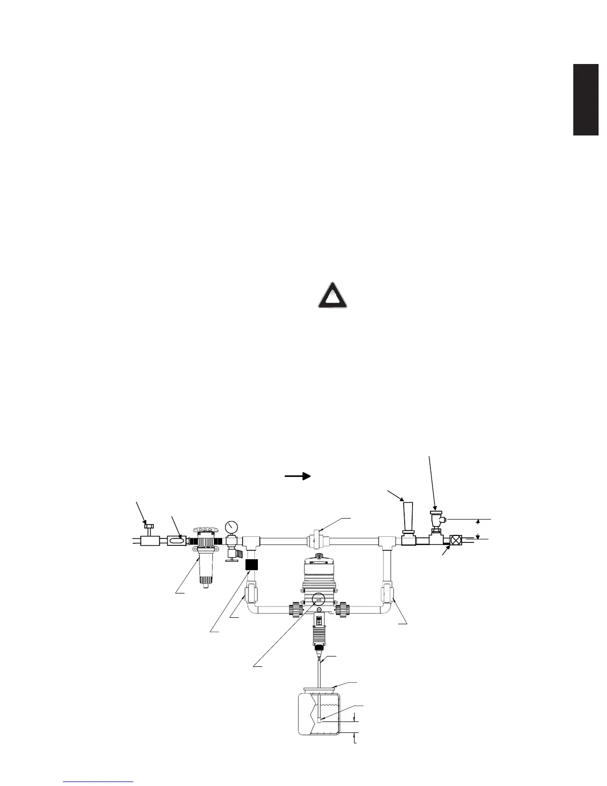
Check System for Leaks and Start-Up Procedures
Open the bypass valve (A), close inlet valve (B) and outlet
valve (C) to prevent fl uid fl ow into the injector. SLOWLY turn on
the main fl uid line. Run fl uid fl ows between 5 -12 gpm (11-45
l/m) through the plumbing system. Open all of the valves located
downstream from your injector to release trapped air. SLOWLY
open the inlet valve (B). Open the outlet valve (C) and close valve
(A). As fl uid travels through the injector, you will hear a “clicking”
sound. Check for leaks and correct if necessary.
COVERED CONTAINER
INLET FILTER
INLET VALVE
(RECOMMENDED)
BYPASS VALVE
(RECOMMENDED)
OUTLET VALVE
(RECOMMENDED)
SUCTION TUBE
SOLUTION FILTER
50 MM
2" REQUIRED
(A)
(B)
(C)
FLOW INDICATOR
BACK FLOW
PREVENTOR
BYPASS
DIRECTION OF FLOW
140 MESH / 104 MICRON
(MINIMUM REQUIRED)
FLOW CONTROL
VALVE @ OUTLET
ANTI-SIPHON
VALVE
(OPTIONAL)
(OPTIONAL)
FLUID HAMMER
ARRESTER
PRESSURE
REGULATOR
(RECOMMENDED)
(RECOMMENDED)
PRESSURE
GAUGE
(OPTIONAL)
(OPTIONAL)
FILL
VALVE
(OPTIONAL)
6" minimum
152.4 mm
PRESSURE SAFETY
DEVICE
(RECOMMENDED)
Installation and Start-up
Fig. 5
Refer to Fig. 4 and Fig. 5
Suggested Installation Diagram
!