Issued July 2024
Body Controller Softw are
Copyright 2024, The Heil Co.
Printed in the U.S.A.
Body Controller Software
116
Automated Side Loader Cortex Controller™ Program 109-0285 (Rev 20210223)
Section 1: CORTEX Controller Hardware
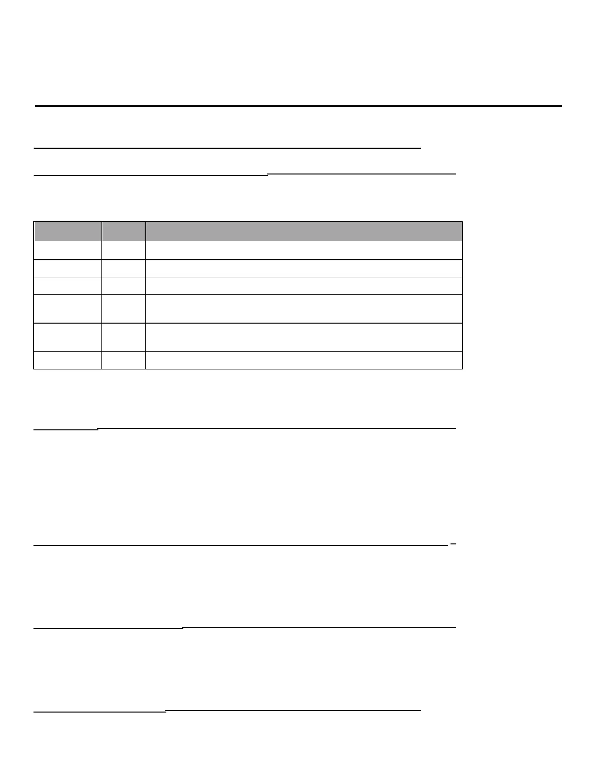
1.01: CORTEX Controller Indicator Lights
The CORTEX Controller used here is a single control unit with 40 Input / Outputs, which operates with a voltage ranging from
(10 to 32) Volt DC. The CORTEX Controller has a three-color LED (Red / Green / Blue) which indicates the current status of the
Controller. The LED Operating Status identifications are detailed in the table below.
Initialization or Reset Checks
No Operating System Loaded
Run with Error
Fatal Error or Stop with Error
Communication OK between 2 Controllers (for 80 I/O CORTEX Controller) *
Note*: LED will flash Blue when there is a good communication between the 2 halves of the Controller. This condition is applicable
only for 80 I/O CORTEX Controllers.
1.02: Inputs
The CORTEX Controller is equipped with the potential of having multiple types of Inputs. Some of which are strictly binary
active high meaning they are activated by a positive 12 Volt signal. Some of the binary inputs can be configured to function as
active low meaning they are activated by a ground signal. Some inputs can be configured as analog and can be used to respond to
a voltage or current range. Unless otherwise specified, all Switches, Proximity, Pressure, Toggle, Push Buttons, etc., used as input
devices to the Controller, supply a +12 Volt signal to their respective inputs to turn the Input ON. One exception to this is an
analog hydraulic oil temperature transmitter.
With an Input ON, the corresponding Input field (with Description and Address) shown on the INSIGHT display will also be ON.
Refer section 5.05 for more details about Diagnostic display options and INSIGHT display tool.
1.03: Outputs
During each cycle the CPU will analyze the status of the inputs, and based upon the logic of the programming, will produce
the appropriate +12 Volt DC outputs.
With an Output ON, the corresponding Output field (with Description and Address) shown on the INSIGHT display will also be
ON.
Refer section 5.05 for more details about Diagnostic display options and INSIGHT display tool.
1.04: Communication Ports
There are 2-CAN and 1-RS232 communication ports in each 40 I/O CORTEX Controllers which will be utilized for the
programming and communication purpose. For an 80 I/O Controller there is total 4-CAN & 2-RS-232 ports. The Serial port (RS-232)
in the Master Controller will be utilized to download user programs via CORTEX Download tool (Downloader 32) and CAN ports in
the Master Controller for communication between Controller and field devices.
1.05: Diagnostic Display
Refer section 5.05 for more details about Diagnostic display options and INSIGHT display tool.