Issued July 2024
Body Controller Softw are
Copyright 2024, The Heil Co.
Printed in the U.S.A.
Body Controller Software
147
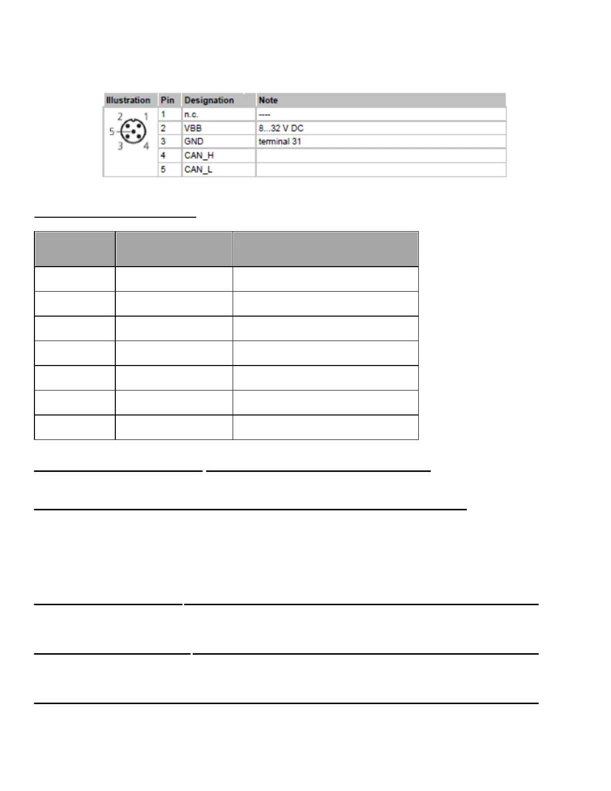
5.05.04: Display Status LED’s:
No Operating system loaded
RUN State (application is running)
STOP State (application stopped)
Application stopped due to under voltage
FATAL ERROR or STOP state with error
Section 6: Diagnostics
6.01: Testing I/O Voltage
To test the voltage at an input or output terminal a Digital Multi Meter is always the best tool.
Incandescent test lights cannot be used to test inputs from certain electronic input devices, the amperage required to light and
incandescent tester may exceed the maximum output of the device. If using a test light it must be an LED type tester. Upon
inspection of the CORTEX CONTROLLER assembly, note that there are through holes in the upper circuit boards. These holes
provide test probe access to the lower I/O terminals.
6.02: Monitoring Input Status
With an Input ON, the corresponding Input field (with Description and Address) located in INSIGHT display will also be ON.
Refer section 5.05 for more details about Diagnostic display options and INSIGHT display tool.
6.03: Monitoring Output Status
With an Output ON, the corresponding Output field (with Description and Address) located in INSIGHT display will also be ON.
Refer section 5.05 for more details about Diagnostic display options and INSIGHT display tool.
6.04: Diagnostic Beep Codes
Each Diagnostic code consists of a two-digit number. When a fault has been set the In-Cab Alarm will sound for 5 seconds,
then pause. Then beep a number of times specifying the first digit of the code, pause for 2 seconds. Then resume to beep a
number of times specifying the second digit of the code. See the following or the decal in the cab for the explanation of each beep