Instructions for Use Air Compressor 37
English / US English
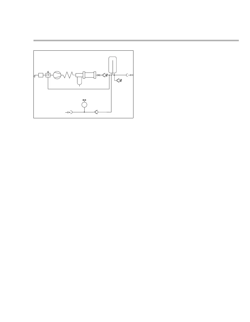
Description
1 Intake filter
2 Control valve
3 Compressor unit
4 Cooling coil
5 Prefilter
6 Condensate trap
7 Diaphragm drier
8 Restrictor nozzle
9 Non-return valve
10 Pressure vessel
11 Medical air outlet
12 Input for standby mode
13 Pressure switch
14 Non-return valve
15 Relief valve
Ambient air is drawn in via the intake filter 1 on the
control valve 2 , condensed in the compressor unit
3 and cooled in the cooling coil 4.
The condensed air is cleaned in the prefilter 5.
Condensate is collected and drained in the
condensate trap 6.
The subsequent diaphragm drier 7 dries the air to a
dew point at least 5 °C (41 °F) below the ambient
temperature.
The dehumidified air flows via the restrictor nozzle
8 and non-return valve 9 to the pressure vessel 10.
Removal occurs via the coupling 11.
The control valve 2 is pressurized with the vessel
pressure and controls the pressure generation
depending on the volume withdrawn.
Compressor with standby mode (optional)
For a compressor with standby mode, the ventilator
draws air from the central gas supply system via the
coupling 12, non-return valve 14 and self-closing
coupling 11. The compressor unit 3 is in standby.
When the pressure in the central gas supply
system falls below 2.7
±0.2 bar (40±3 psi), the
pressure switch 13 switches the compressor unit 3
on.
When the pressure in the central gas supply
system rises above 3.2±0.2 bar (46±3 psi), the
pressure switch 13 switches the compressor unit 3
off again.
The relief valve 15 protects the unit against
excessively high pressure from the central gas
supply system.
034
 Loading...