Section 2
General Description
Color Coding
Each connection, valve, gauge, and flowmeter is labeled and color-coded
for the appropriate gas, as shown in the table below.
GAS SYSTEM COLOR CODING
GAS MARKING USA ISO Germany
Air AIR Yellow Black/White
Checkered
Yellow
Carbon Dioxide CO
2
Gray Gray Black
Nitrous Oxide N
2
O Blue Blue Gray
Oxygen O
2
Green White Blue
Oxygen-Helium O
2
-He Brown/Green
Diagonal Stripes
Brown/White
Diagonal Stripes
N/A
Gas Entry Via
Pipeline
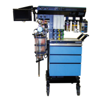
Gas from the hospital pipelines enters the Narkomed 2B through hoses
connected to indexed pipeline inlets located on the side of the flowmeter
housing. The indexed connector system reduces the risk of delivering the
wrong gas to a patient by preventing incorrect connection of gas pipes.
The inlets include check valves, which prevent back flow leakage into
the atmosphere (when supply hoses are not connected) or into the
attached supply hoses (when reserve cylinders are in use). Each pipeline
connection is equipped with a filter to prevent foreign material from
entering the internal gas piping of the Narkomed 2B. Pipeline gases
should be supplied at 50–55 psi.
Pipeline Pressure
Gauges
The anesthesia machine includes pipeline pressure gauges for oxygen
and nitrous oxide. On machines equipped with air, a pipeline pressure
gauge for air is also included. The gauges are located directly below their
corresponding flowmeters and flow control valves, and are labeled and
color-coded for their respective gases. Concentric scales in psi and kPa
indicate the pipeline supply pressure. A typical pressure gauge and
flowmeter arrangement is shown in the following figure.
2-2
 Loading...