Section 2
General Description
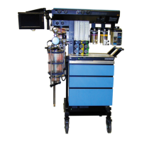
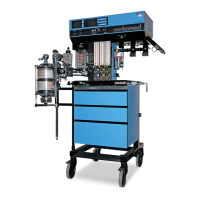
I:E RATIO CONTROL
I:E RATIO DISPLAY
FREQUENCY
CONTROL
FREQUENCY
DISPLAY
INSPIRATORY FLOW GAUGE
INSPIRATORY
FLOW CONTROL
VENTILATOR
ON-OFF
CONTROL
TIDAL VOLUME
CONTROL
PRESSURE
LIMIT CONTROL
TIDAL
VOLUME
SETTING INDICATOR
BELLOWS CANISTER
BREATHING CIRCUIT
CONNECTOR
OP91018c
FREQUENCY
/min
I:E RATIO
INSPIRATORY
FLOW
VENTILATOR
ON
FAULT
1400
1200
1000
800
600
400
200
PRESET TIDAL VOLUME (ml)
EXTENDED RANGE
ACCESS
EXTENDED
RANGE
AV2+
INSPIRATORY PRESSURE LIMIT
cmH
2
O
TIDAL VOLUME
PUSH TO TURN
Main Switch Panel
The main switch panel is located between the ventilator bellows and
flowmeter bank.
System Power
Switch
The SYSTEM POWER switch on the Narkomed 2B has two positions: ON
and STANDBY.IntheON position, the gas (pneumatic) and electric
power circuits are actuated, and the green LED indicator adjacent to the
switch illuminates. In the STANDBY position, the switch shuts down the
gas supplies, the monitoring system, and all electrical power to the
machine except the convenience receptacles and battery charging circuit.
AC Power Failure
Indicator
The yellow AC POWER FAIL LED signals a disruption of AC power. The
LED is illuminated whenever the battery supplies power to the
monitoring system and the electronic ventilator. A single tone also
sounds when AC power is first disrupted. If the anesthesia machine’s
backup battery is completely discharged, the AC power failure indicator
does not have power and will not function.
2-20
 Loading...