9023810 - 2nd edition - September 2005
Page 9 of 42
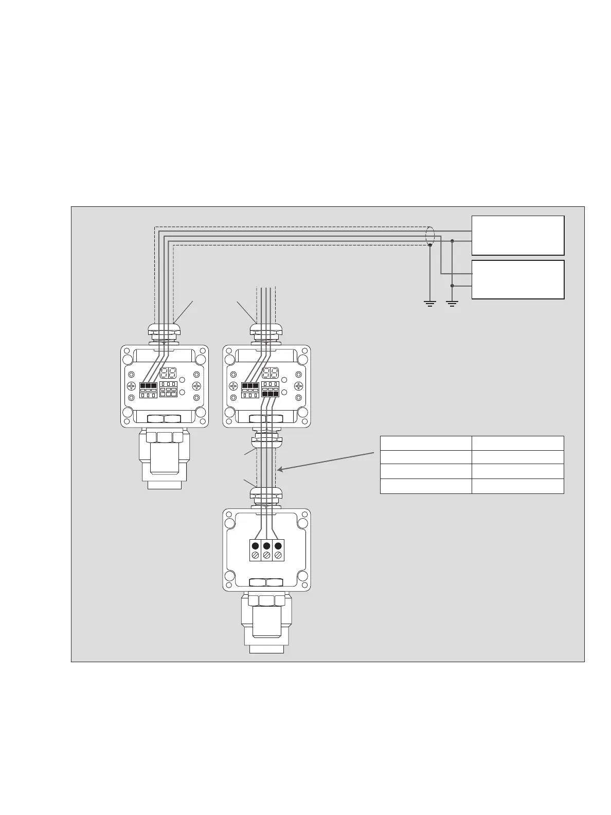
Installing Transmitter
●
Remove cover of the transmitter.
●
Connection between transmitter and central controller as shown.
Type XTR 0090 and XTR 0091:
●
Connection between sensing head and transmitter as shown.
— The power supply may also be an integral part of the controller unit.
—
PEX 3000, all types PEX 3000, types XTR 0090 and XTR 0091
Connection to central controller: Connection to sensing head
Connect terminal +24V to +24 Volt Connect terminal br/br to terminal 1
Connect terminal SIG to 4 bis 20 mA input Connect terminal ge/yw to terminal 2
Connect terminal 0 V to 0 Volt Connect terminal sw/bk to terminal 3
00323810_1_en.eps
+24 Volts
0 Volt
Cable screen
contacted within
the cable gland
PEX 3000
Type XTR 0000,
XTR 0001,
XTR 0010
und XTR 0011
Cable screen
contacted within
the cable gland
PEX 3000
Type XTR 0090,
XTR 0091
Sensing head
Polytron SE Ex
Power supply
24 V ±20 %,
0.15 A
4 to 20 mA
0 mA
Controller Unit
➀➁➂
max. cable length
50 m
100 m
150 m
core cross-section
0.5 mm
2
1.0 mm
2
1.5 mm
2