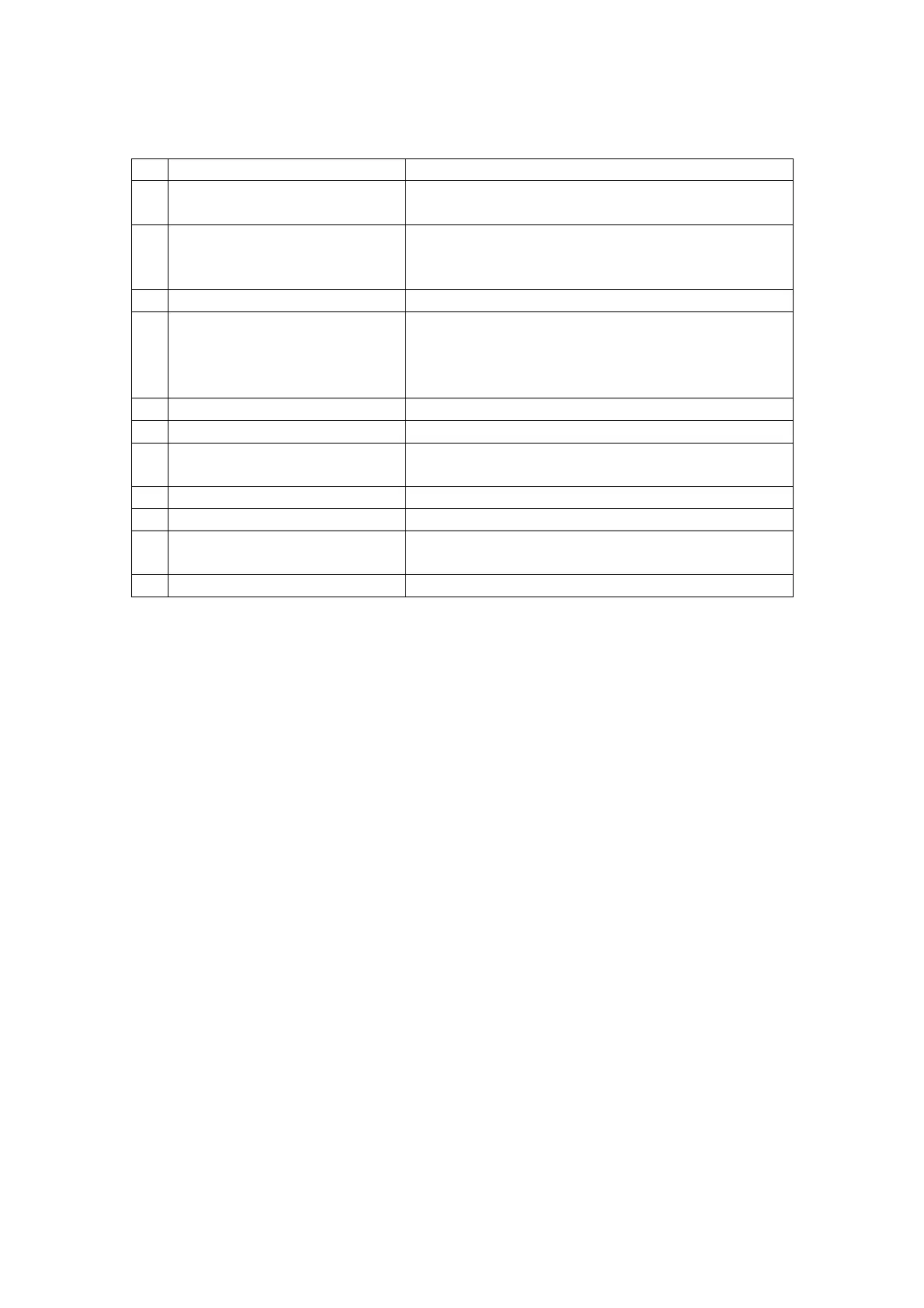
Fault finding
Fault condition Repair procedure
1 Control unit non operational Check and replace input fuse if necessary.
Check third party electrical supply.
2 Display blank Check cable connection between main circuit
board and display board.
Adjust contrast potentiometer on display board.
3 Self test routine fails Replace display board
4 Under-range displayed Check transmitter connections.
Check and measure loop current.
Jumpers A to E missing, Fit jumpers (mA
version)
5 24Vdc output failed Check loading is < 100mA
6 24Vdc driver output failed Check loading is < 100mA
7 AC output failed Check loading is < 500mA
Replace fuse.
8 Incorrect measuring range Check display board DIL switch
9 Alarms rising or falling Check main board DIL switch
10 No TWA information Set switch 6 to ‘ON’ position on the display
board.
11 Water ingress Check sealing ring is in place
Glossary
AC/DC Alternating current/Direct current
DIL switch Dual inline switch
LED Light emitting diode
LCD Liquid crystal display
TWA Time weighted average
PC Personal computer
TP1 Test point 1
TP2 Test point 2
mA Milliamps
Vdc Volts DC
DVM Digital volt meter
VR1 Variable resistor (Potentiometer)
PCB Printed circuit board
SK2 Socket 2
Issue 4 03/09/04
19 of 29