Maintenance
Page 22 of 42
9023810 - 2nd edition - September 2005
Maintenance
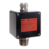
Sensor Replacement
— Use sensors only which are listed in the order list page 27.
Type XTR 0000, XTR 0001: Ex-Sensor PR M, part-no. 68 09 225,
Type XTR 0010, XTR 0011: Ex-Sensor LC M, part-no. 68 10 350.
● Observe national regulations for the installation of electrical apparatus in potenti-
ally explosive atmospheres devices (in Europe EN 60 079-14).
● De-energise transmitter or remove the corresponding channel module of the cen-
tral controller.
● Disconnect the sensor leads from the terminals. Use screw driver (3 mm width) or
special tool to open the spring terminals. (see page 10 about handling spring ter-
minals).
● Energise transmitter again and re-install the corresponding channel module of the
central controller.
● Observe warm-up time of the new sensor of about 10 minutes.
Attention:
The transmitter must be de-energised before disconnecting the sensor.
Otherwise then explosion protection is infringed and the sensor might be
impaired during connecting procedure.
● Loosen four screws on the top of the transmitter’s housing and remove the up-
per section.
● Unscrew hexagon nut of the old sensor.
● Remove old Ex-Sensor out of the housing and replace by a new Ex-sensor. Shor-
ten the sensor leads to 55 mm, strip approx. 6 mm insulation and fix the attached
isolated ferrules (Zoller+Fröhlich, Type: V3AE0003 or equivalent). This ensures
an IP-rating of IP 30 if the transmitter housing is opened for maintenance purpo-
ses.
● Screw in new sensor through the corresponding and secure with locking
sealant, e.g. Loctite No. 221. To maintain the IP-rating observe that the sensor’s
O-ring is tightly fitted.
● Connect the sensor’s leads (brown, yellow, black) to the corresponding spring
terminals marked br/br, ge/yw und sw/bk. Use screw driver (3 mm width) or spe-
cial tool to open the spring terminals. (see page X about handling spring termi-
nals).
● Observe the atmosphere is free of dust and re-install the upper section of the
housing by means of the four screws.
Attention:
After replacement of the Ex-sensor the transmitter must be calibrated (see
transmitter calibration, page 17).

 Loading...