Function SW1
1
SW1
2
SW1
3
SW1
4
SW1
5
SW1
6
SW1
7
SW1
8
A1 rising ON
A1 latching OFF
A2 rising ON
A2 latching OFF
A3 rising ON
A3 latching OFF
Fault latching OFF
A2 special
* see Note
OFF
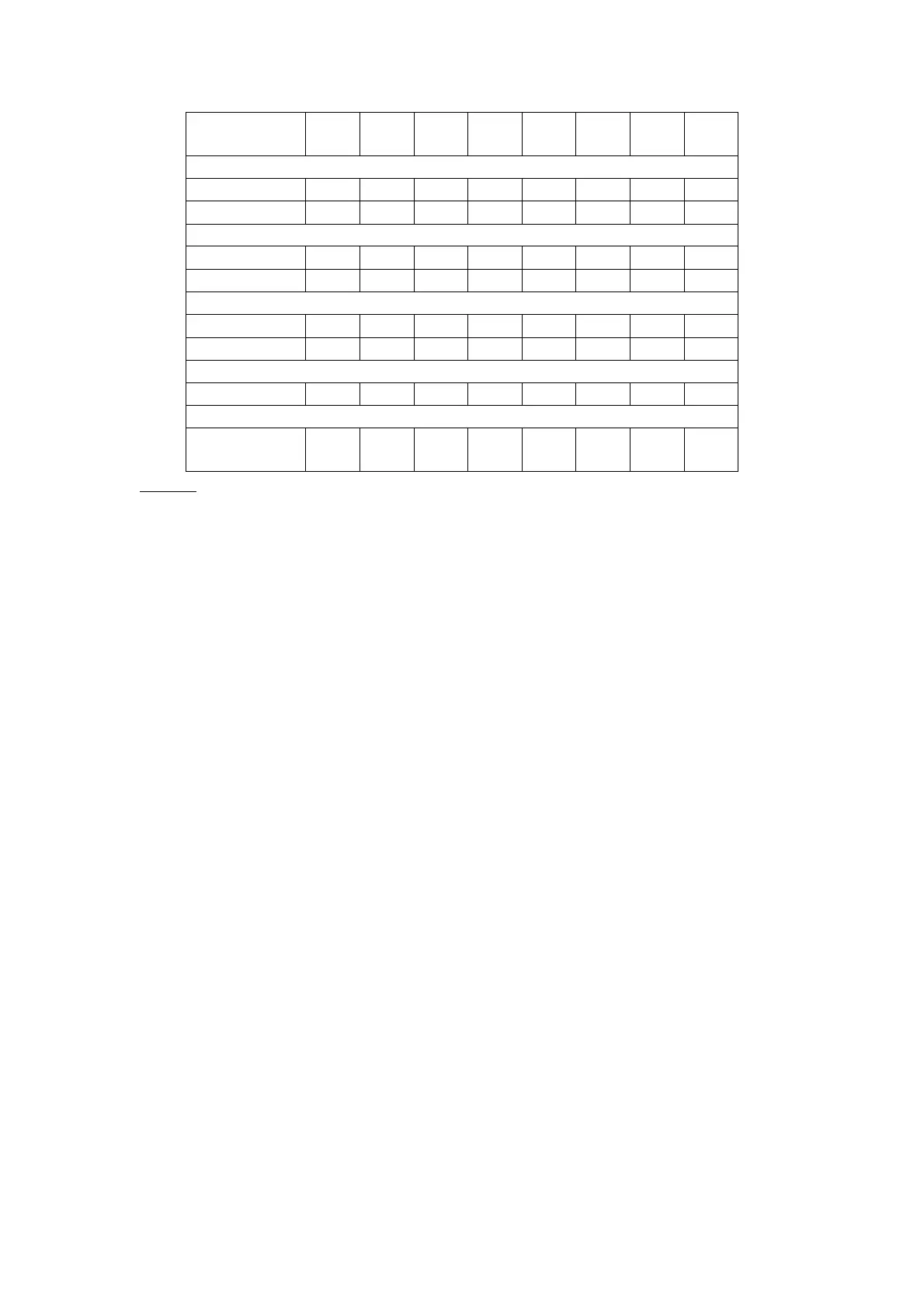
Table 3
* Note: SW1–8 allows the A2 relay to be used as a switch for an audible alarm. In the
‘OFF’ position the latched condition (silencing the klaxon) can be cleared during an
alarm condition (gas still present).
Set latching/non-latching alarm relay mode
Alarm levels 1, 2, 3 and Fault can be set as either latching or non-latching. Each alarm
level is independently set via a DIL switch on the main circuit board. Table 3 shows
the relationship between the alarm condition and the DIL switch position.
Calibration
Zero adjustment
The control unit has no zero adjustment. The signal from the transmitter at 4mA (±
32µA) will automatically indicate zero gas. Should a gas value be indicated then the
loop calibration must be adjusted at the transmitter.
Span adjustment
The control unit only needs a single point calibration. An input value of between 50%
and 90% of the measuring range should be set as an input. Potentiometer FSD (VR1)
should be adjusted to set the loop calibration.
The display can be used directly to set the calibration. Where the control unit has no
display then a DVM can be connected across TP1 and TP2. Table 1 shows the
relationship between a mV value on the DVM and an analogue value.
Issue 4 03/09/04
12 of 29