Installing Transmitter
Page 8 of 42
9023810 - 2nd edition - September 2005
Mounting the transmitter
●
By means of fours screws (diameter 4 mm) through the holes of the housing
(drilling template see page 29).
Installing Electrical Connections
Connection between transmitter and controller unit
The maximum cable length for loads of 250 Ohms can be extracted from the follo-
wing table:
●
By means of 3-core screened cable, (braided screen, cover
≥
80 %), outer
diameter min. 7 mm, max. 12 mm. Connect Shielding as short as possible to earth
clamp of the controller unit.
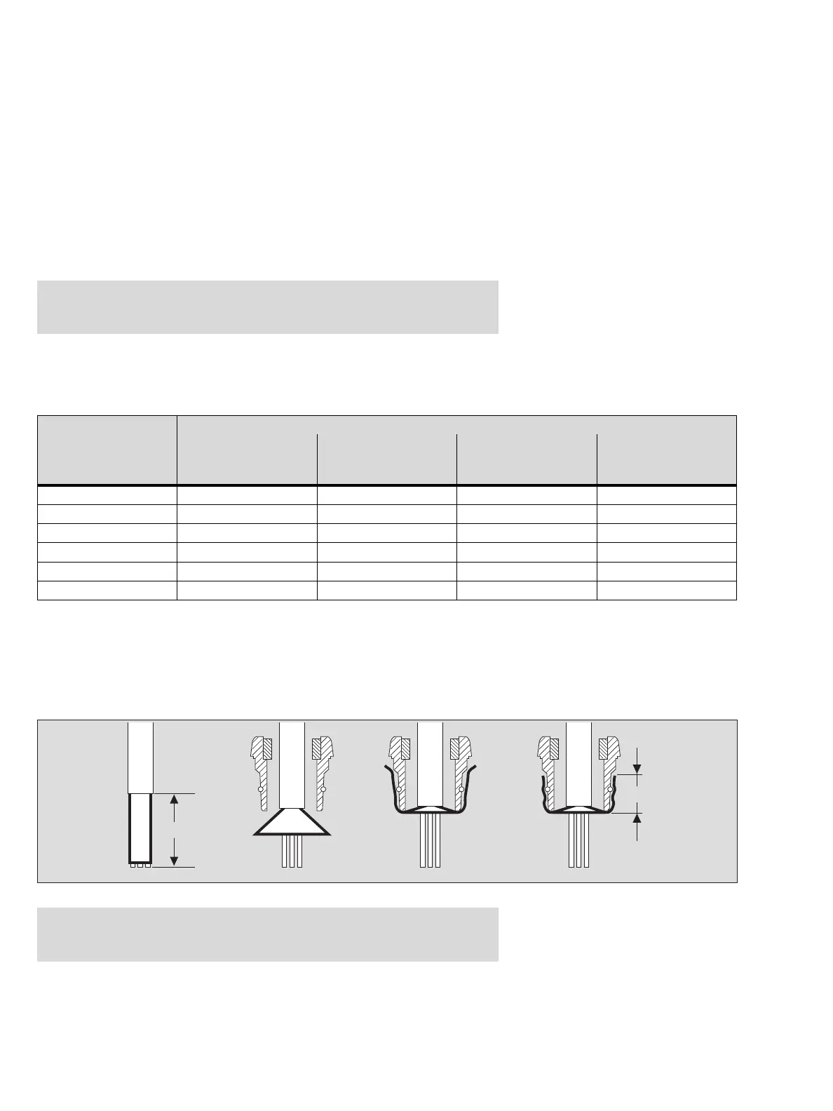
●
By means of the connecting cone within the cable gland the cable-screen has to
be contacted to the internal conductive surface of the enclosure as shown. With
this the required RF-immunity according to EN 50 270 is ensured.
— Electrical wiring is only to be laid and connected by an expert paying attention
to the pertinent regulations and laws concerning electrical equipment in poten-
tially explosive atmospheres as well as the approval conditions.
core cross-section
minimum supply
voltage at
controller side
0.5 mm
2
(36 Ohms/km)
0.75 mm
2
(24 Ohms/km)
1.0 mm
2
(18 Ohms/km)
1.5 mm
2
(12 Ohms/km)
18 V 416 m 625 m 833 m 1249 m
20 V 555 m 833 m 1110 m 1666 m
22 V 694 m 1041 m 1388 m 2082 m
24 V 833 m 1249 m 1666 m 2498 m
26 V 972 m 1457 m 1943 m 2915 m
28 V 1110 m 1666 m 2221 m 3331 m
Remark:
The cable gland is explicitly approved for fixed installations and outer cable
diameters between 7 and 12 mm.
ca. 55 mm
ca. 12 mm
00223810_1_de.eps