Operation
Page 20 of 42
9023810 - 2nd edition - September 2005
Operation
— Corresponding to the gas concentration the transmitter produces is a current bet-
ween 4 and 20 mA, especially
Shut downs
In the event of shut-downs, e.g. when performing maintenance and inspection work,
the transmitter is ready for use again after approx. 10 minutes (sensor warm-up time)
following a renewed switch-on of the system.
● Calibrate the transmitter again if necessary.
Use of dust filter
Type XTR 0000:
A dust filter can be used with the Ex-sensor PR M (see order list, part-number
68 10 537).
This is simply pressed into the opening of the sensor in front of the sinter disk and is
self-clamping. This dust filter will increase the sensor’s response time only slightly.
There is nearly no influence on the sensor’s sensitivity by the dust filter.
If a dust filter is used it has also to be used during the calibration procedure. It is
recommended to use a freshly installed dust filter before starting the calibration
procedure.
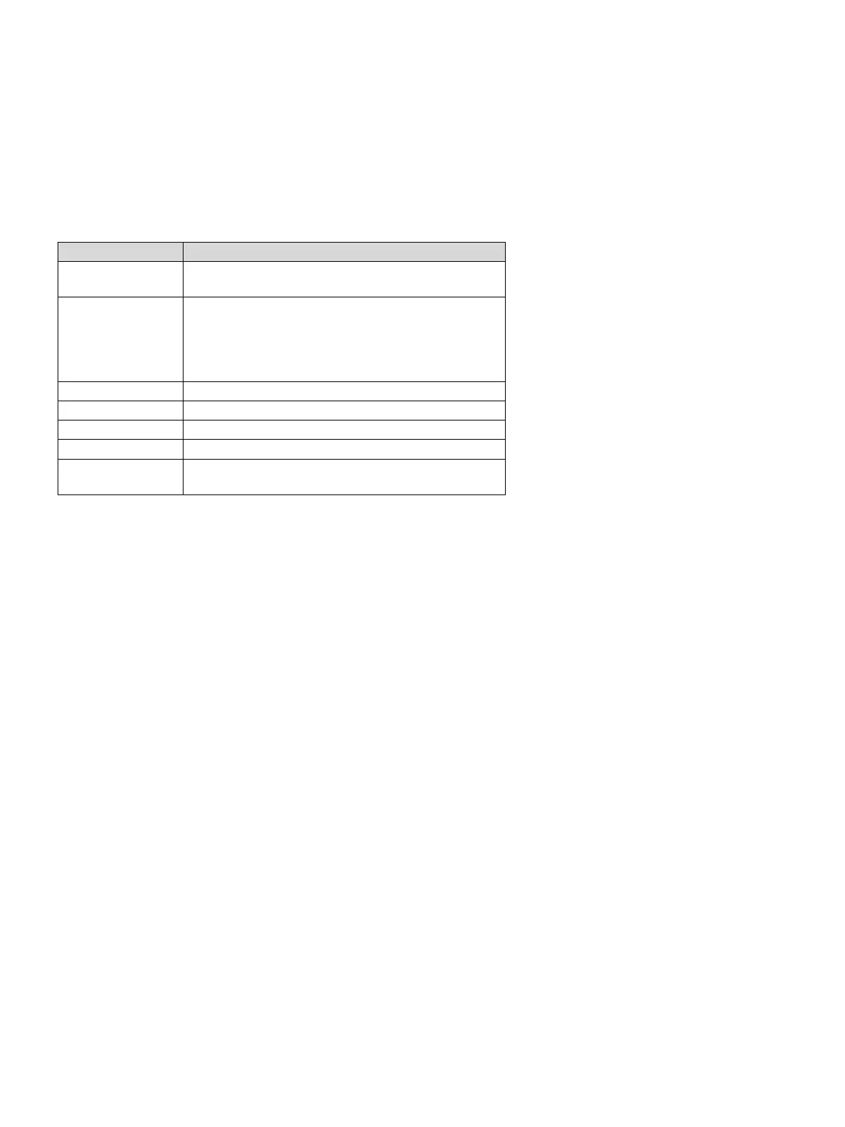
Output current Meaning
0 mA Cable is broken or power supply has failed
1 mA Failure:
● Zero underrange by more than 5 % of full scale value
● Failure of electronics
● Broken cable or short-circuit in the sensor circuit
3.4 mA Calibration signal
3.8 mA to 20.5 mA Output signal normal operation
4 mA Output signal zero
20 mA Output signal full scale value
20.5 mA Overrange by more than 3 % of full scale value