13
Electrical connections
— The cable resistances given apply for a load resistance of 250 Ω. Higher
load resistances can drastically reduce the permissible cable resistance!
When other barriers have been selected, care must be taken that the volt-
ages on the transmitter do not fall below the following values when barrier
parameters and cable resistance are taken into account:
16.5 V for a current of 3 mA and 8.0 V for a current of 22 mA.
If HART communication is to be used, the HART specifications must also
be observed.
The maximum possible cable lengths can be found in the table on page 19.
In each case, use the line marked "Number of transmitters = 1".
— Connect shielding to earth point and/or 0 V (Ex i).
Installing the transmitters in explosion-hazard areas of zone 2
— Use only supply units or a safety barrier of the device category 3.
— Only supply units or safety barriers with the following characteristics may
be used: U
O
(V
OC
) ≤ 30 V, I
O
(I
SC
) ≤ 0.3 A, P
O
≤ 700 mW.
— Take care that the maximum permissible capacitance and inductance of
connections to the supply unit are not exceeded, also taking the cable into
account.
The safety-related input parameters of the transmitter are:
C
i
= 5 nF, L
i
= 50 µH.
The maximum possible cable lengths can be found in the table on page 21.
In this table, select the line, " Number of transmitters = 1".
CAUTION
The category 1 marking has to be cut out from the rating-plate label. Once
the unit has been used after installation in the above manner, it may never
be installed in explosion-hazard areas of zone 0 or zone 1 (device category 1
or 2). Explosion hazard!
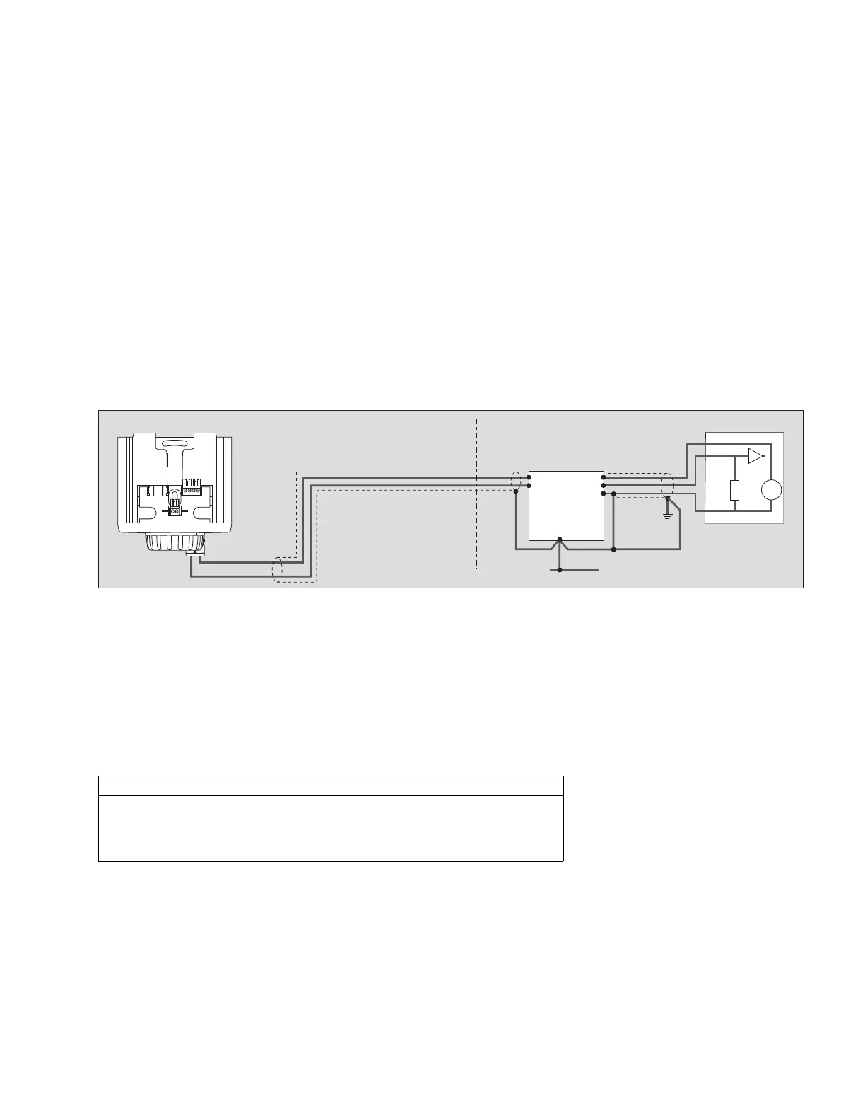
00923758_1_en .eps
Non-explosion-hazard areaExplosion-hazard area, zone 0, 1 or Div. 1
Safety barrier
Control unit
Ex i
PA
Earth point
4 ... 20 mA
0 V
+
–
+
4 to 20 mA
+24 V