33
Installing accessories
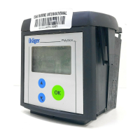
4 Plug the connection cable into the male connector behind the display, en-
suring that the cable is not twisted.
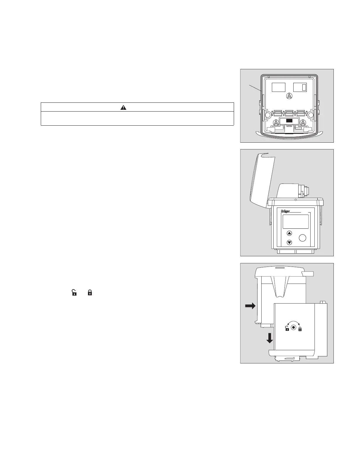
Place the relay module on the measuring unit and snap it into position on
both sides.
In order to make this step easier, the relay cover may be removed.
After connecting the relay module to the measuring unit:
6 Fit the cover again.
Mounting the measuring unit with relay module
7 Slide the measuring unit with relay module into the docking station and low-
er it into position, see page 25.
8 Turn the eccentric catches clockwise with an Allen key to lock the measur-
ing unit ( = approx. 180
o
).
Connecting the devices to be switched
The relay module has three 3 potential-free outputs, each capable of switch-
ing 250 V / 5 A:
— A1 relay (switches when the A1 gas alarm is active)
— A2 relay (switches when the A2 gas alarm is active)
— Fault relay (switches in the case of a device fault)
Setting the alarm thresholds: see page 64.
Connect the devices to be switched to the cable sockets.
Cable sockets of the following types may be used:
CAUTION
5 Take care that pressure is applied only to the sleeve of measuring unit.
Pressure on the inner structure can damage the unit.
— Binder Type 692 Part No. 99–0210–00–04
— Amphenol Type C16-1 Part No. T 3109–001
— Hirschmann Type CA3 LD Part No. 934–125–100
— Dräger Safety Part No. 18 90 086
03123758_1.eps
4
5
03223758_1.eps
Polytron
OK
6