5327.400 Vapor 2000 05/99 Function Description Page 2
For internal use only. Copyright reserved.
GBF5327400T01.fm 28.08.01
Function Description
1Handwheel settings
1.1 Handwheel set to “0” (off)
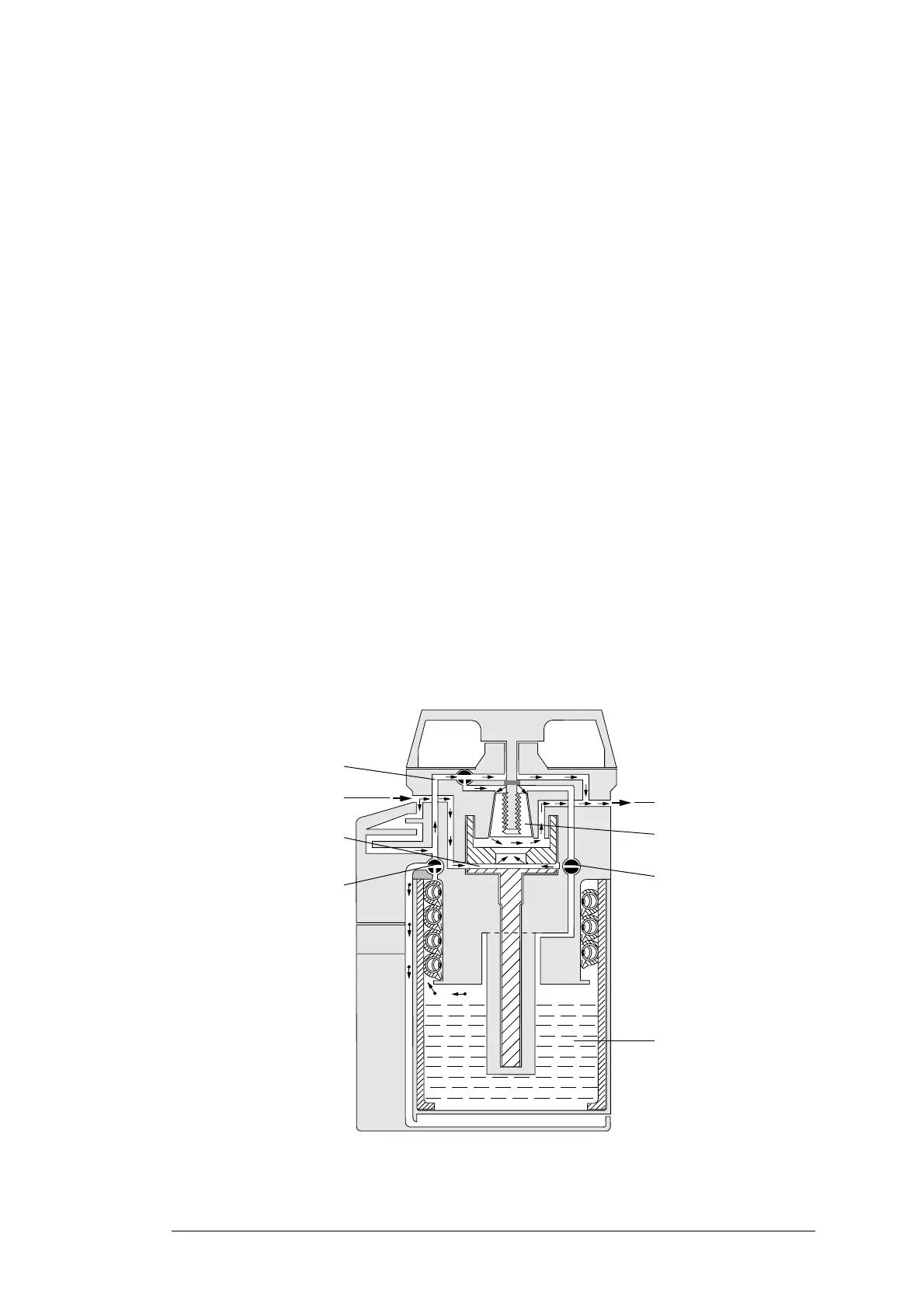
The fresh gas (→) flows from the vaporizer inlet to the vaporizer chamber bypass and through
the vaporizer chamber bypass from the outside to the inside. In parallel, a portion of the fresh
gas flows by way of an additional bypass and the flow control cone to the vaporizer outlet.
The vaporizer chamber is completely isolated from the gas flow by the valve (switching state a
and b). No anaesthetic can enter the flow control valves or the fresh gas.
A small hole in the valve (switching state a) vents the vaporizer chamber to prevent pressure
from building up.
As a result of temperature and pressure fluctuations, diffusion and pressure compensation
may cause small amount of anaesthetic vapour to escape. Ducts and buffer volume delay this
process.
If the Vapor 2000 is positioned at a tilt, anaesthetic may leak out of the vaporizer chamber
through the vent hole.
Fig. 1: Handwheel set to “0” (off)
Vaporizer inlet
Additional bypass
Vaporizer chamber bypass
Vaporizer outlet
Flow control cone
Vaporizer chamber
Valve (switching state a)
Valve (switching state b)