DRC 242-A 2007-08-03 Page 11 DC3 with SEM Installation Instructions
11. Connect the white wire (primary trigger input)
The primary trigger input (WHITE WIRE) is typically set up to monitor the vehicle’s doors. The
event recorder will then record an event each time a door is opened or closed. In many cases, the dome
light circuit is the best place to make this connection as it is usually connected to all of the vehicle’s doors.
If you can find the location of the dome light circuit under the dashboard, you’ll save yourself the trouble
of routing the wire under the headliner. If not, then you can simply make the connection at the dome light.
Some vehicles use a common door switch circuit (connecting all doors and the dome light) while other
vehicles use an individual door switch circuit (connecting each door to a controller and the controller to
the dome light). Refer to your vehicle’s wiring schematics for more information. If you’re not sure, make
the connection at the dome light.
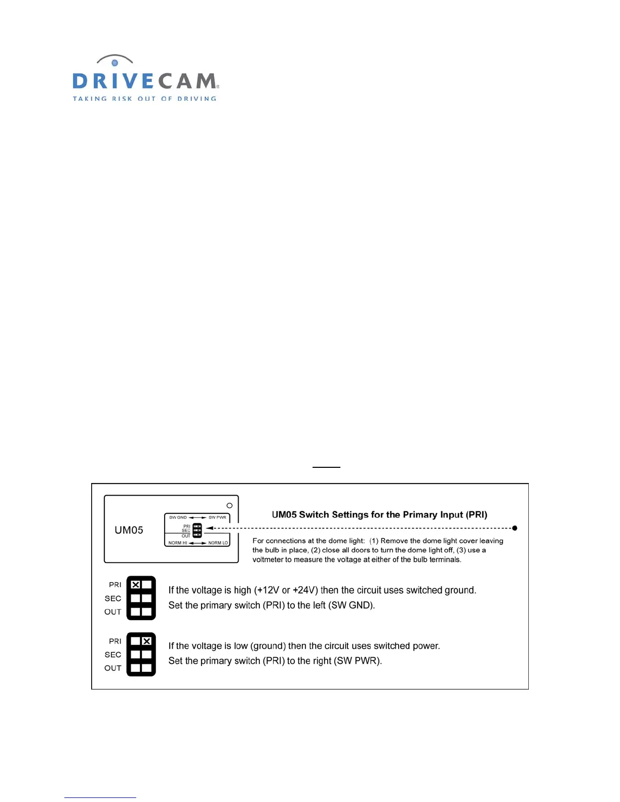
Testing the Dome Light Circuit
Use the following steps to determine the type of bulb circuit (switched ground or switched power) and
make the appropriate primary (PRI) switch setting on the Universal Module (UM05).
Step 1 Remove the dome light cover, leaving the bulb in place.
Step 2 Turn the load “OFF” (i.e. close all doors to turn off the dome light).
Step 3 Use a voltmeter to measure the voltage at either
of the bulb terminals.
Step 4 Turn the load “ON” (i.e. open a door to turn on the dome light).