DRC 242-A 2007-08-03 Page 19 DC3 with SEM Installation Instructions
18. Using the Output Feature (blue & yellow wires)
The DriveCam Event Recorder has the ability to control other devices within the vehicle. The event
recorder has an output signal that will change from its normal state whenever an event is triggered. After
saving that event, the output returns to its normal state.
With the UM05 device, this function is greatly enhanced. The user has the ability to determine the
voltage level of the output as well as whether the output’s normal state is high or low. The output can
provide TTL level logic signals, or it can be used to operate loads drawing up to 2 Amperes of current.
These loads can be either resistive (lights) or inductive (relays or motors).
Due to the wide variety of ways that this output may be used, it is impossible to cover all potential
applications. The instructions and examples contained here should be considered a general guide. Your
particular application will determine the actual wiring configuration.
NOTE: Due to the variety of ways the Output feature may be used it is recommended that
any wiring of this device be done by a qualified automotive electrician.
CAUTION: Although every effort has been made to prevent it, incorrect wiring of the
Output feature may cause damage to your UM05.
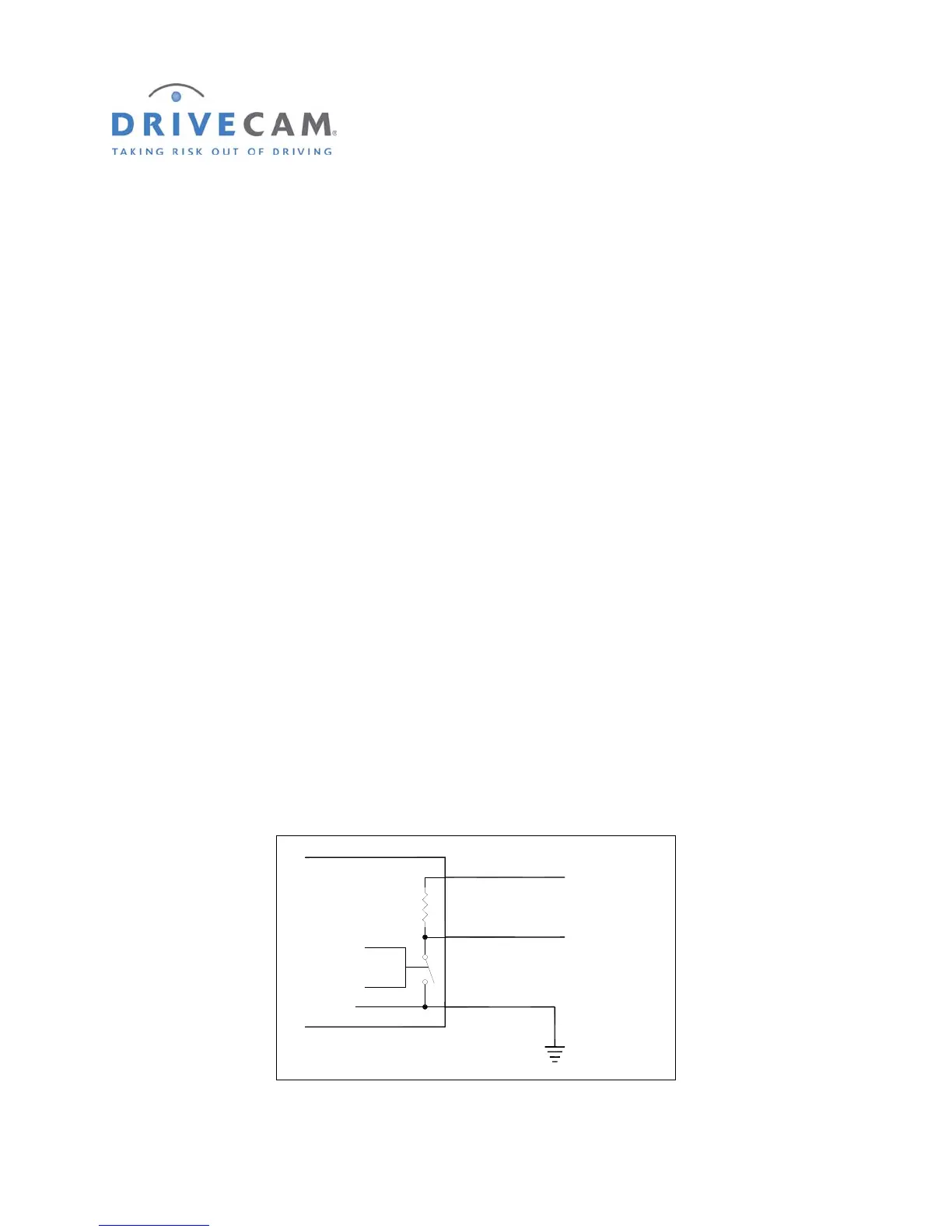
General Operation
The Output feature of the UM05 acts like a switch. One side of this switch is permanently connected to
the black wire (ground) of the UM switch cable. The other side of the switch is connected to the blue
wire. Also connected to the blue wire is a 1,800 Ohm (1.8KΩ) resistor whose opposite side is connected
to the yellow wire. This yellow wire needs to be wired to a voltage source if you want the voltage at the
blue wire to go up when the switch is open. Figure 1 shows a block diagram of the UM05 output circuit.
Control
Yellow Wire
Blue Wire
Black Wire
(Always Connected to Ground)
1,800 Ohms
1/2 Watt
UM05
Ground
F
IGURE 1 UM05 OUTPUT BLOCK DIAGRAM