DRC 242-A 2007-08-03 Page 13 DC3 with SEM Installation Instructions
12. Connect the orange wire (secondary trigger input)
The secondary trigger input (ORANGE WIRE) can be connected to one of several different
electronic devices within the vehicle (e.g. taxi meter, car alarm, horn, button, etc.). The event
recorder will then record an event each time the device is activated. In most cases, it is connected to a
concealed switch that can be manually triggered by the driver in an emergency. Most standard constant
state switches (toggles, push on/push off) or momentary pushbuttons may be used.
Testing the Switch Circuit
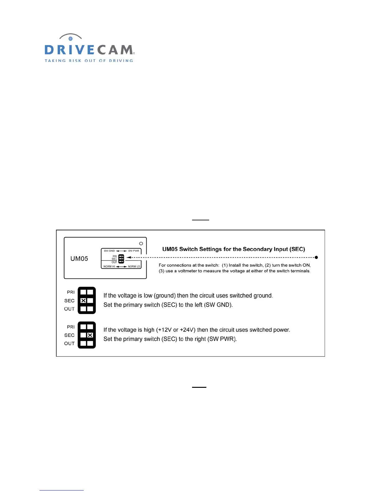
Use the following steps to determine the type of switch circuit (switched ground or switched power) and
make the appropriate secondary (SEC) switch settings on the Universal Module (UM05).
Step 1 Install the switch then turn the switch “ON”.
Step 2 Use a voltmeter to measure the voltage at either
of the switch terminals.
Step 3 Turn the switch “OFF”.
Step 4 Use a voltmeter to measure the voltage at each
of the switch terminals.
One terminal will remain the same as measured in the previous step – the other terminal voltage
will have changed. The connection must be made to the terminal that changed voltage.
Step 5 Connect the orange wire to the switch.
Make sure you are connecting to the correct side of the switch circuit as measured in step 4.