DRC 242-A 2007-08-03 Page 23 DC3 with SEM Installation Instructions
UM05 Switch Setting
Norm Lo Norm Hi
DriveCam Event OFF ON
No Event ON OFF
TABLE 2 OPERATING A LOAD FROM THE BLUE WIRE
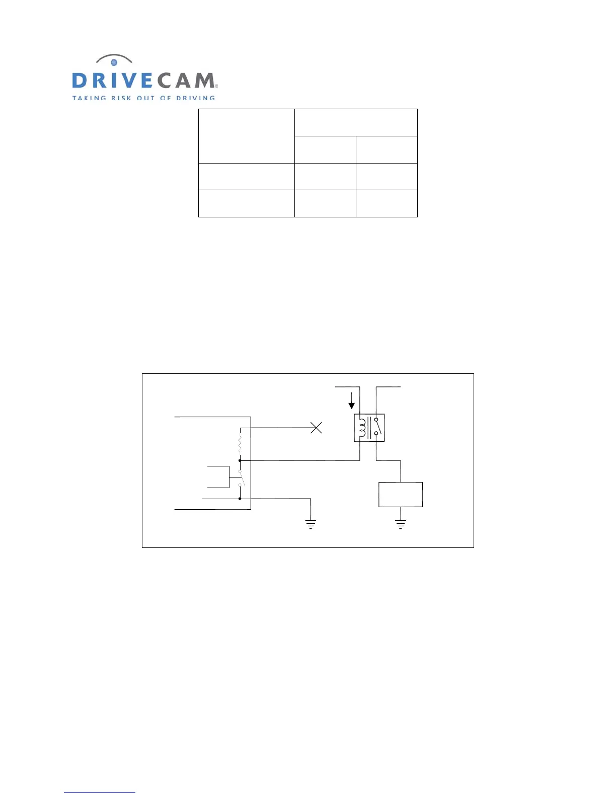
Example 3: Triggering heavy current or chassis ground devices
Example 3 is actually very much like example 2, but the load that is operated by the UM05 is a relay.
This configuration is used if the load current of the device is greater than 2 Amps, or if the device has a
chassis ground (no separate ground wire). The UM05 OUT switch settings for this example, a Normally
Open (NO) relay, are those shown in table 2. If a Normally closed (NC) relay were used the table would
be reversed.
Control
Yellow Wire
Blue Wire
Black Wire
(Always Connected to Ground)
1,800 Ohms
1/2 Watt
UM05
Ground
+12V
Relay
I < 2 Amps
_
(No Connection)
+12V
User
Load
F
IGURE 6 HEAVY CURRENT OR CHASSIS GROUND DEVICES
Example 4: Triggering a GPS or other electronic device that needs more drive current
In some rare cases, the UM05 may be connected as shown in example 1, but there is not enough current
supplied by the UM05 to drive the input. The drive current may be increased by duplicating the job of the
UM05’s internal supply resistor with an external one (see figure 7). If this is done, three precautions must
be adhered to:
First, the current through the resistor must be 2 Amps or less. For a 12 Volt electrical system this means
the resistor should be greater than 8 Ohms. To prevent other problems, the resistor value should be as
high as possible and still pass the current needed for the application.