DRC 242-A 2007-08-03 Page 22 DC3 with SEM Installation Instructions
0
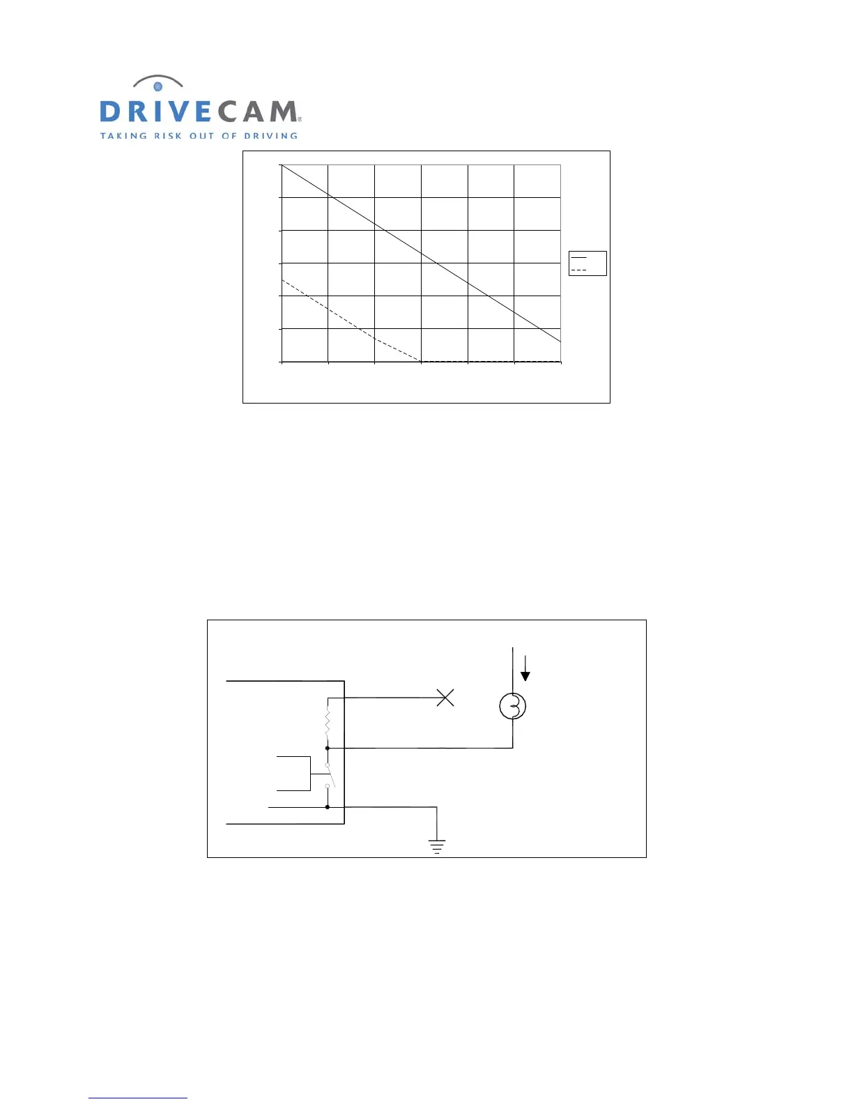
2
4
6
8
10
12
0123456
Current (mA)
Voltage (V)
12V
5V
F
IGURE 4 VOLTAGE VS. CURRENT AT THE BLUE WIRE
Example 2: Triggering devices that use up to 2 Amps and have a separate ground wire
There are many auxiliary devices for vehicles that fit into this category. Auxiliary lights, warning buzzers,
and relays are some of the possible devices. If the total current draw is less than 2 Amps and the device
has a separate ground wire (not chassis grounded) this method can be used. In this situation, the yellow
supply wire is not used. Instead the device to be operated has its positive wire connected to a +12 Volt
source and the negative wire is connected to the blue wire as shown in figure 5.
Control
Yellow Wire
Blue Wire
Black Wire
(Always Connected to Ground)
1,800 Ohms
1/2 Watt
UM05
Ground
+12V
Lamp or other Load
I < 2 Amps
_
(No Connection)
F
IGURE 5 EXAMPLE 2, LOAD WITH A SEPARATE GROUND
In example 2, because we are switching the ground wire, operation of the device may seem backwards.
To turn the device ON we need the UM05 switch to turn ON which will make the voltage at the blue wire
go LOW. Table 2 shows how to set the UM05 OUT switch to achieve the desired function at the load.