Tamarisk
®
Camera Control Software User Guide
5.3 VIDEO
Figure 29 illustrates the Video tab. The Video tab comprised of two task panes, Analog Video and
Digital Video. Factory default settings are Analog Video Enabled and Digital Video Camera Link
enabled. Analog Video and Parallel Digital Video are mutually exclusive. To save changes to the
video output, the user must click on Save Settings before moving to another tab or closing the Camera
Control Software application.
5.3.1 Video Overview
Within the Camera Control Software, the video output of the camera is broken into the Settings,
Video, Colorization, AGC, and the Pan and Zoom tabs. Since all of these tabs are related to each
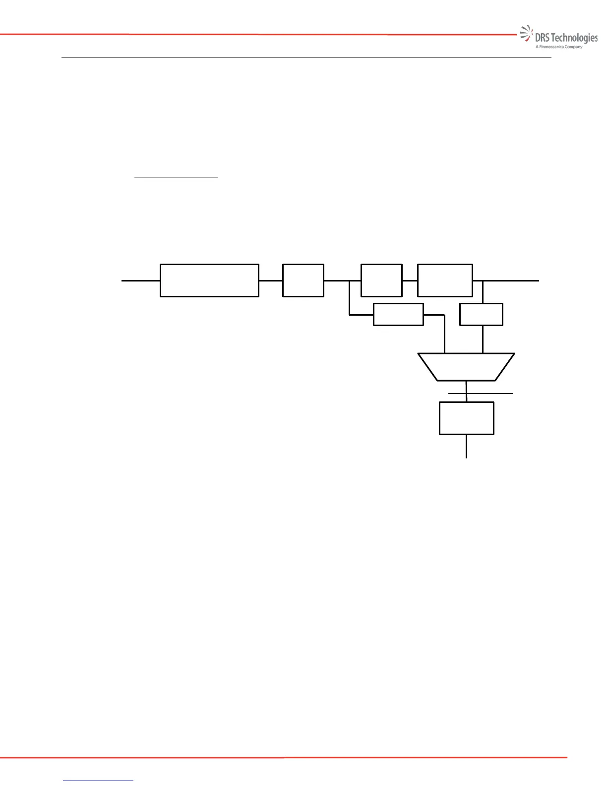
other a high level explanation of the camera video functions is helpful. Figure 28 is a block
diagram of the video chain.
Figure 28: Video Block Diagram
On the left side of the block diagram, the detector (or FPA) output feeds into the rate adaptation,
Non Uniformity Correction, and Bad Pixel Replacement block. The output of this block is a 14-
bit corrected image and it feeds into the Zoom block.
The zoom block can perform up to a 4X digital zoom and also allows the user to perform a digital
pan and tilt. The Zoom block feeds into the Frame buffer block.
The frame buffer block performs the white-hot, black-hot and allows the user to change the image
orientation. The 14-bit output of the Frame buffer block feeds into the Digital Video Selection
block and the AGC block.
The AGC block allows the user to select several different AGC modes. The AGC block also
converts the 14-bit video to 8-bit digital video. The output of the AGC block feeds into the
Symbology block.
The Symbology block allows the user to display camera information on-screen. The output of the
symbology block is input to the digital to analog converter (DAC) block where the 8-bit digital
Digital Video
To Video DAC
(Analog Video)
Rate Adapt, NUC, BPR
Zoom
AGC
Symbology
Raw Detector
Output
14-bit
Colorization
To Digital Video
To Parallel Digital Video
 Loading...