Tamarisk
®
Camera Control Software User Guide
2 HARDWARE SETUP
2.1 HARDWARE CONFIGURATION
In this section, three different configurations for viewing your camera’s output video will be
presented, including solutions for both analog and digital video. Although the physical interface may
vary from camera to camera, the schema outlined below will remain valid for the products listed in
section 1.1 above.
Table 1, presents three different approaches for viewing your camera’s output video as well as the
recommended hardware to support that given approach. An illustration is provided to document each
connection and demonstrate what the given set-up may look like.
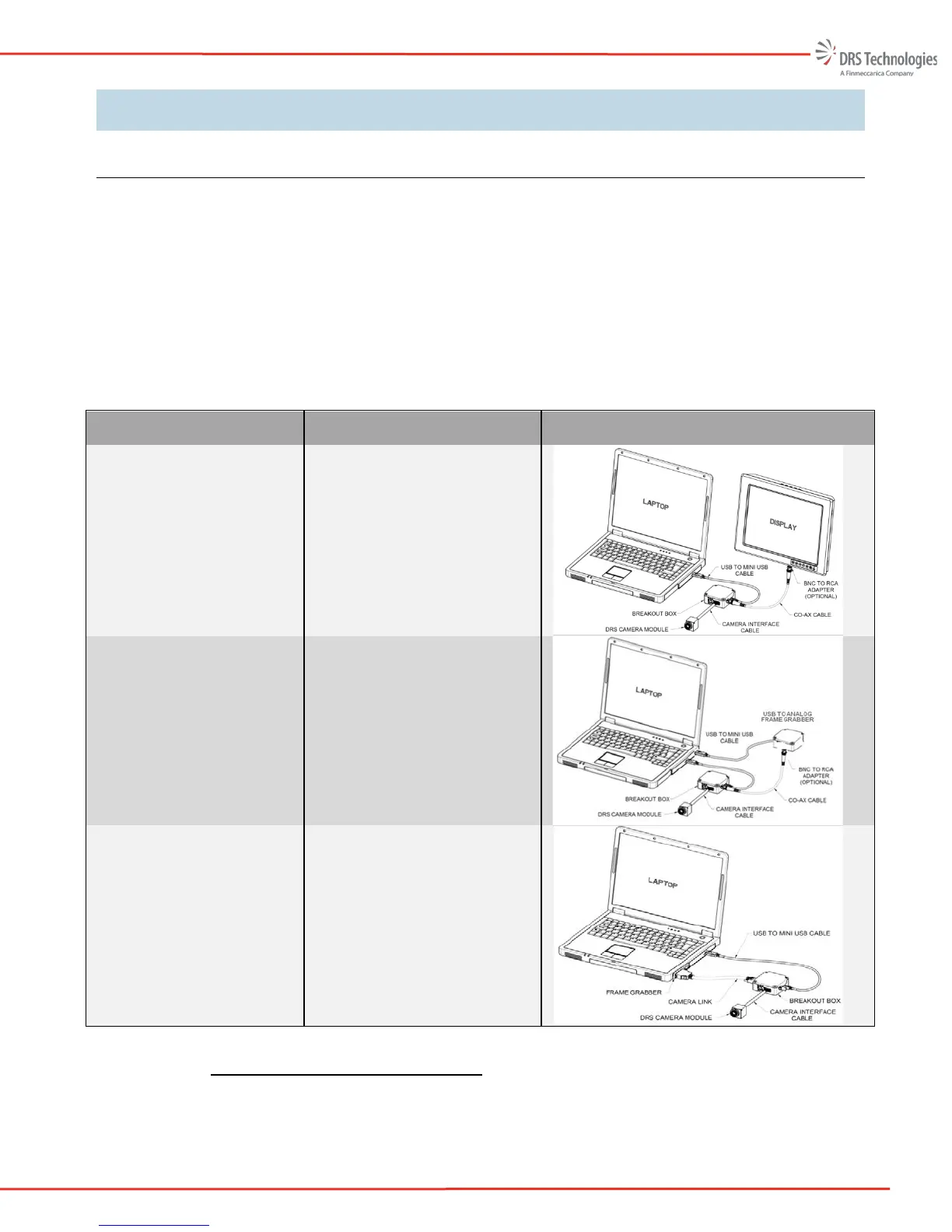
Table 1. Hardware Configuration Set-up Overview
Display Configuration Required Hardware Illustration
Analog video to an external
monitor
Laptop
Analog Display
USB to USB mini cable
Camera Module
Camera Interface Cable
Camera break out box
Coax cable
Analog video displayed on
the PC
Laptop
USB to analog frame grabber
USB to USB mini cable
Camera Module
Camera Interface Cable
Camera break out box
Coax cable
Camera Link (digital) video
displayed on the PC
Laptop
Camera Link frame grabber
Camera Link cable
USB to USB mini cable
Camera Module
Camera Interface Cable
Camera break out box
2.1.1 Connecting to an Analog Monitor
The simplest way to evaluate the camera is to configure the hardware as shown in Figure 1. The
user simply needs to apply power and connect the RS-170 cable to an analog monitor. For some